


Control panel wiring assembly covers how conductors are routed, terminated, labeled and bonded within an enclosure to meet documented requirements. The scope includes physical build execution, not concept work. It excludes design engineering and enclosure fabrication. System programming also falls outside assembly responsibility.
Quality wiring forms the foundation of lifecycle reliability. Precise routing reduces abrasion and heat exposure. Correct termination maintains signal integrity and torque retention. Clear labeling speeds service and lowers error risk.
Solid bonding protects personnel and stabilizes electrical reference, improving maintenance efficiency and equipment uptime. Consistent workmanship simplifies inspections and supports long-term compliance across operating environments globally.
Get Your Free Sample!
Explore our custom services now. Email us at sales@wiringo.com for more details.
How Control Panel Wiring Quality Affects Reliability, Safety, And Costs
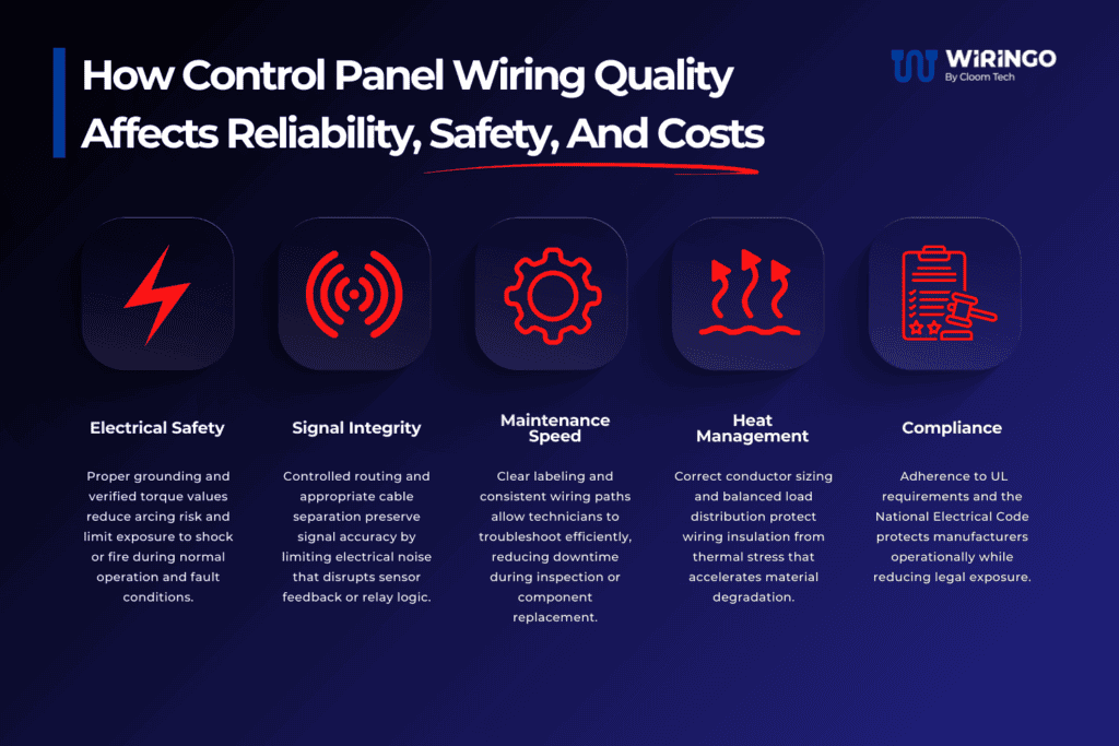
Control panel wiring quality directly influences how a control panel performs over its service life. Assembly decisions made during build determine safety margins and fault tolerance. These choices also shape long-term operating costs.
- Electrical Safety: Proper grounding and verified torque values reduce arcing risk and limit exposure to shock or fire during normal operation and fault conditions.
- Signal Integrity and Performance: Controlled routing and proper separation between power and signal cables preserve signal accuracy. This limits the electrical noise that can disrupt sensor feedback, control logic, and overall system stability.
- Equipment Lifespan: Secure, well-torqued terminations maintain uniform contact pressure, reducing electrical and thermal stress. This mechanical stability ensures consistent performance as electrical demand and ambient temperatures change, directly extending the equipment’s operational life.
- Maintenance Efficiency: Clear, consistent labeling and orderly wiring paths allow technicians to troubleshoot and perform service efficiently. This high serviceability reduces downtime during inspections or component replacement, lowering operational costs.
- Heat Management: Correct conductor sizing and routing that allows for airflow to protect wiring insulation from thermal stress. Preventing heat buildup avoids the material degradation that leads to premature failure.
- Compliance and Risk Reduction: Adhering to standards such as UL and the National Electrical Code (NEC) is non-negotiable. It simplifies integration, ensures operational compliance, and reduces the manufacturer’s legal exposure.
Ultimately, superior wiring integrity lowers the total cost of ownership by reducing failure frequency, simplifying service, and maximizing equipment uptime.
Key Components Of Control Panel Wiring Assembly
Each element of the control panel wiring assembly contributes to reliability through direct physical cause and electrical effect. Execution quality at this level determines how conductors behave under load, heat, and mechanical stress.
- Wire Gauge and Insulation: Proper sizing supports current capacity and limits thermal buildup during sustained operation.
- Routing Paths and Bend Radius: Controlled routing protects conductor life and maintains signal stability under vibration.
- Terminal Torque: Verified torque values secure connections and prevent resistive heating at termination points.
- Shield Handling: Correct shield termination improves noise immunity in sensitive circuits.
- Grounding and Bonding: Effective grounding establishes reference voltage stability and improves personnel safety.
- Labeling: Clear identification supports faster installation and reduces wiring errors during service.
- Power and Signal Separation: Physical separation lowers electromagnetic interference that disrupts low-level signals.
- Strain Relief: Mechanical support extends termination lifespan by limiting pull force at connection points
Get Your Free Sample!
Explore our custom services now. Email us at sales@wiringo.com for more details.
Step-By-Step Process Of Control Panel Wiring Assembly
Control panel wiring assembly follows a controlled sequence that aligns documentation, physical build, and verification. Each step limits variation and reduces downstream correction.
1. Review Of Schematics And BOM Alignment
This step confirms that drawings and documentation support accurate execution before work begins. Early review prevents misinterpretation that would otherwise surface during termination.
- Confirm Clarity: Verify that symbols and callouts are readable and unambiguous.
- Identify Missing Callouts: Check for absent wire numbers, device tags, or termination references.
- Flag Conflicts: Detects symbol mismatches or termination inconsistencies before build.
2. Component Mounting And Physical Layout
Component placement establishes mechanical stability and thermal behavior inside the enclosure. Layout decisions also affect service access during maintenance.
- Heat Zones: Position heat-generating devices to avoid local temperature buildup.
- Clearance: Maintain required spacing around components for airflow and access.
- Serviceability: Place devices so that replacement does not disturb adjacent wiring.
- Rail Spacing: Apply consistent DIN rail spacing to support orderly wiring paths.
3. Wire Routing & Preparation
Routing and preparation determine conductor life and electrical performance under load. Errors introduced here propagate throughout the assembly.
- Wire Cutting: Cut conductors to length without excess slack or tension.
- Stripping Control: Remove insulation without damaging conductor strands.
- Ferrule Application: Apply ferrules where required to stabilize terminations.
- Internal Harnessing: Bundle conductors to control movement within the panel.
- Color Identification: Use color coding to indicate voltage class or function.
4. Termination & Labeling
Termination quality defines electrical stability at every connection point. Labeling accuracy supports traceability during installation and service.
- Torque Application: Apply manufacturer-specified torque values at terminals.
- Label Placement: Position labels for visibility after installation.
- Strip Length Control: Avoid over-stripping that exposes excess conductor.
- Lug Selection: Match lugs to conductor size and terminal type.
5. Testing and Verification
Testing confirms that the physical build matches documented intent. Verification reduces the risk of latent faults entering service.
- Continuity Checks: Verify point-to-point connections electrically.
- Load Testing: Apply load where applicable to observe behavior.
- Functional Checks: Confirm control logic responds as expected.
- Documentation: Record results to support traceability and compliance.
6. Final Inspection And Packaging
Final inspection ensures the assembly is complete and ready for installation. Packaging condition affects handling and startup readiness.
- Cleanliness: Remove debris or residue from the enclosure.
- Label Verification: Confirm all identifiers are present and legible.
- Packaging Prep: Protect the panel for transport and installation.
Control Panel Wiring Mistakes (And How To Avoid Them)
Control panel wiring issues often originate during assembly when process control or documentation is weak. The following conditions are directly linked to failure risk.
Oversized Wire Bundles
- Mistake: Packing conductors too densely restricts airflow.
- Solution: Use controlled spacing and appropriately sized wireways to support thermal management.
Poor Grounding Strategy
- Mistake: Inconsistent or improper grounding destabilizes the reference voltage.
- Solution: Implement a unified grounding strategy to improve the stability and safety of the control system.
Inconsistent or Missing Labeling
- Mistake: Absent or unclear identifiers dramatically slow down troubleshooting.
- Solution: Apply clear, durable, and consistently placed labels to improve service accuracy.
Power and Signal Cross-Talk
- Mistake: Routing low-level signal cables parallel to high-power lines introduces interference.
- Solution: Maintain physical separation and use shielded cables where necessary to protect signal integrity.
Improper Terminations
- Mistake: Using incorrect ferrules, lugs, or failing to provide strain relief weakens mechanical support.
- Solution: Use the correct components and provide strain relief to protect terminal connections from vibration and pulling forces.
Tight Bend Radius
- Mistake: Routing wires with sharp bends stresses insulation and conductors.
- Solution: Adhere to the manufacturer’s specified minimum bend radius to extend wiring life.
Lack of Standards Adherence
- Mistake: Ignoring UL and IEC standards creates significant compliance and safety risks.
- Solution: Build in accordance with proven standards to ensure acceptance and safe operation.
Absence of Documented Work Instructions
- Mistake: Relying on tribal knowledge leads to inconsistent builds.
- Solution: Use documented, version-controlled work instructions to reduce variation.
Unqualified Assemblers
- Mistake: Untrained personnel can introduce hidden defects.
- Solution: Employ assemblers certified to standards like IPC/WHMA-620 to improve build consistency.
Inadequate Testing
- Mistake: Skipping 100% verification allows latent faults to enter service.
- Solution: Use automated testing to verify every connection and create a traceable record.
Poor Material Control
- Mistake: Uncontrolled material sourcing can lead to the use of substandard or incorrect components.
- Solution: Maintain a stable and qualified supply chain to eliminate substitution risks.
Weak Engineering Support
- Mistake: Assembly teams without engineering access can misinterpret drawings.
- Solution: Ensure a direct line of communication with engineering to quickly resolve schematic or design issues.
What To Look For In A Control Panel Wiring Assembly Partner
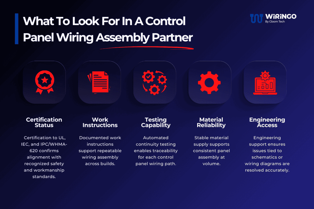
Selecting a control panel wiring assembly partner requires objective criteria that can be verified through documentation or an audit. Capability at this level affects reliability, compliance, and long-term support.
- Certification Status: UL, IEC, and IPC/WHMA-620 certifications confirm alignment with recognized safety and workmanship standards.
- Work Instructions: Documented work instructions support repeatable wiring assembly across builds.
- Testing Capability: Automated continuity testing enables traceability for each control panel wiring path.
- Material Reliability: Stable material supply supports consistent panel assembly at volume.
- Engineering Access: Engineering support ensures issues tied to schematics or wiring diagrams are resolved accurately.
Why OEMs Choose Wiringo For Control Panel Wiring Assembly
OEMs choose Wiringo for control panel wiring assembly because execution quality remains consistent across industrial control panel builds. Clean routing and disciplined workmanship support stable wiring performance inside each control panel.
A solid understanding of industrial environments guides material selection and routing decisions during panel assembly. Materials engineering expertise helps ensure that conductors and insulation meet electrical and environmental requirements.
Turnkey mechanical and wiring assembly reduces handoff risk during production. Fast collaboration with engineering teams supports repeatable quality as builds scale from early units to large runs.
Get Your Free Sample!
Explore our custom services now. Email us at sales@wiringo.com for more details.