Automotive Wiring Harness Wire: The Ultimate Guide on Vehicle Wires

Short out wire connectors

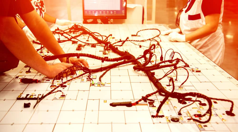
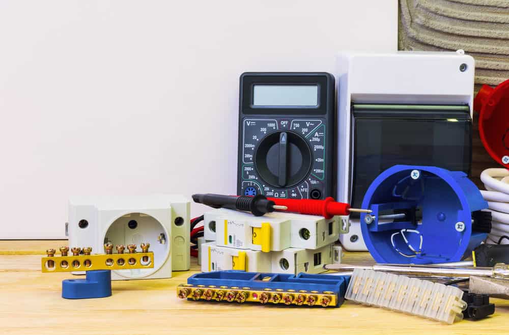
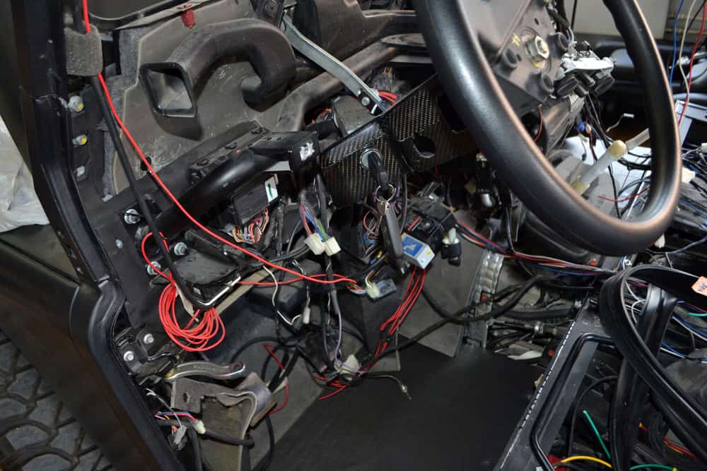
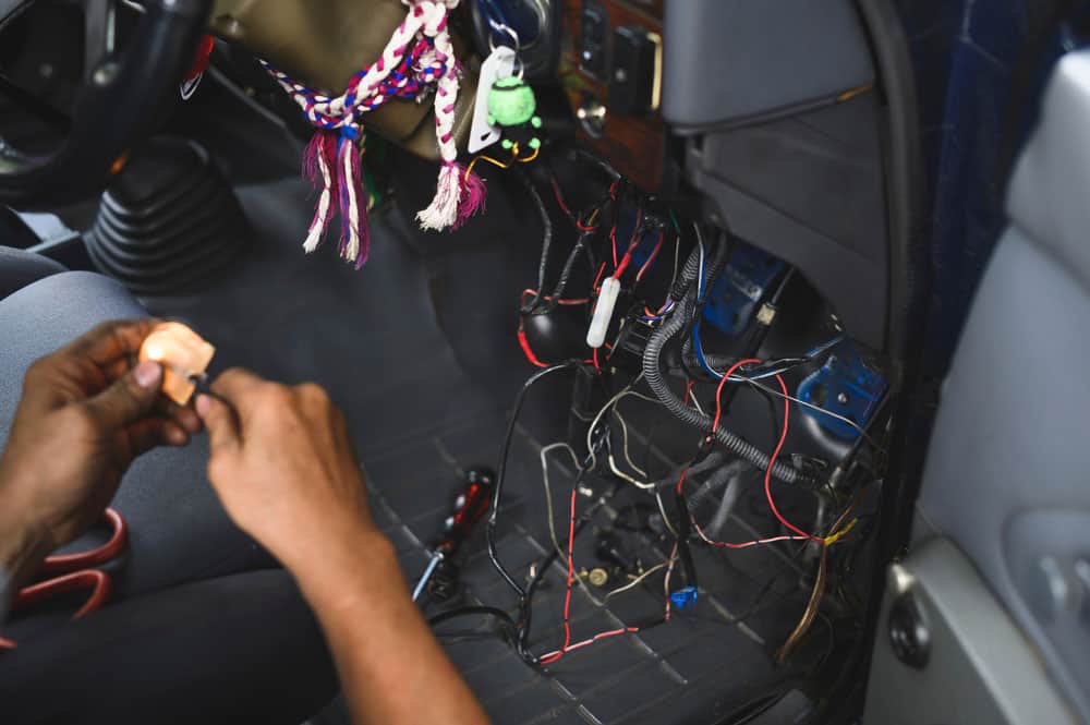
If you pride yourself on exploring your car’s mechanism, you’re probably aware of the vehicle’s wiring. However, if you’re new, this could be a challenging experience and you are supposed to begin with the term, automotive wiring harness wire.

What Is Automotive Wire?

Put it in simple terms; an automotive wire is simply a wire that’s best suited for automotive wire harness purposes.

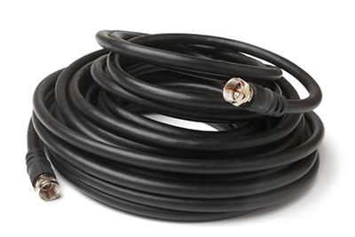
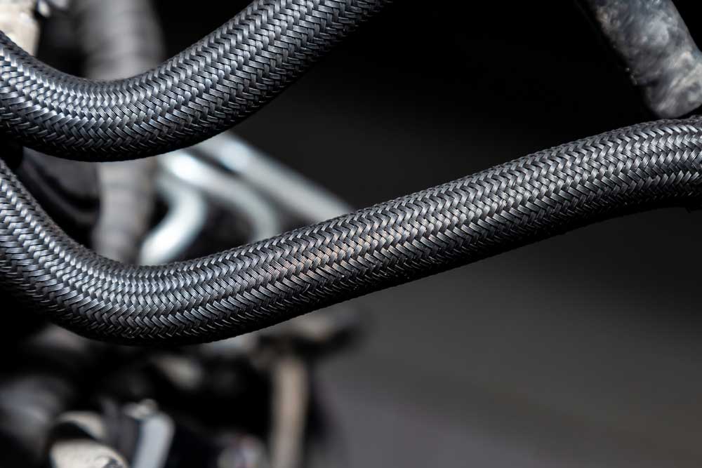
Different types of automotive wires or cables are designed to serve specific purposes. The most common wires you’re likely to come across are the brake, speaker, primary, and battery cable.

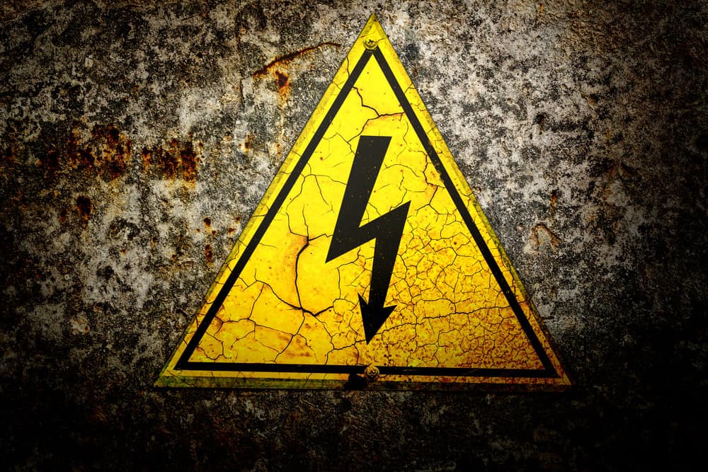
If you pick the wrong type of wire for a specific application, it will lead to system failures in your car. Furthermore, improper Wiring could result in an engine fire. 

Also, as a side note, a wire thicker than gauge 8 is referred to as a cable.
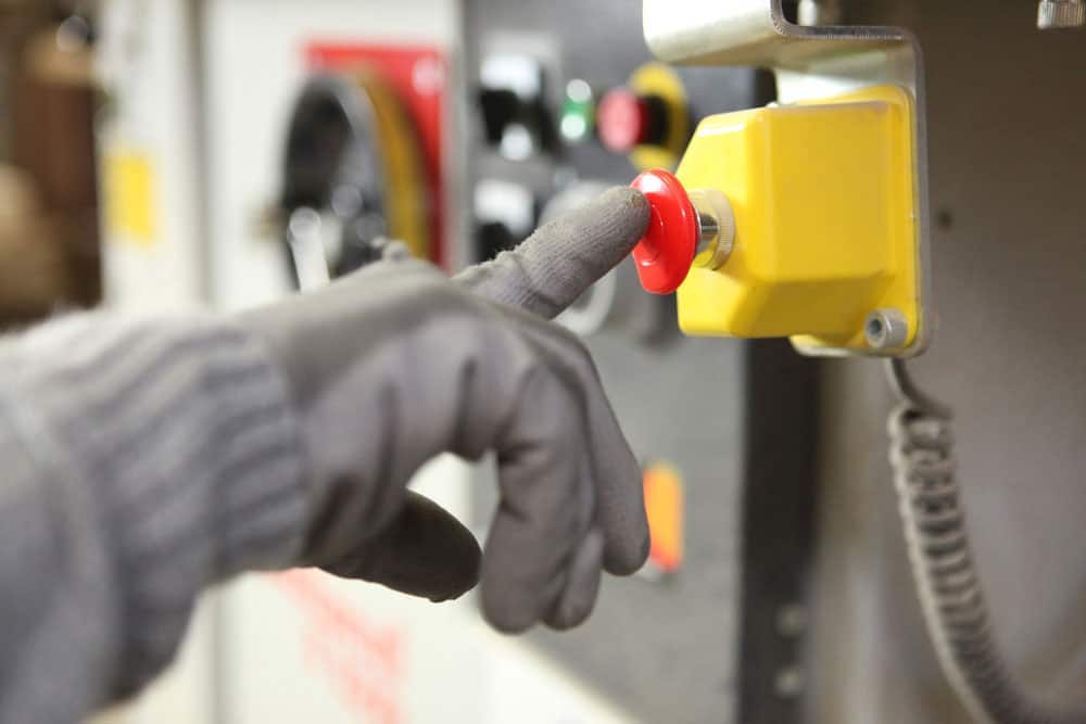
Engine fire

Engine fire

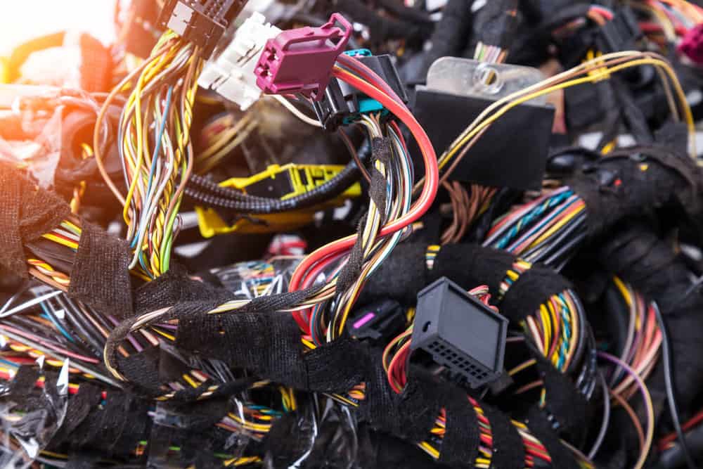
Different Types of Automotive Wires and Cables

The following are different wires used in vehicles.

GPT or Primary Wire or Main Wire

This wire is probably the most common one you’ll come across in any vehicle’s wiring system. The primary wire (GPT) has a multi-strand core with flexible insulation to allow it to fit through tight spaces. They’re mainly used for interior wiring purposes. They’re used primarily for internal wiring purposes. GPT wires should not be exposed to the outdoors for prolonged periods.

Primary wires can endure temperatures of up to 176 Fahrenheit. They can also withstand chemicals, acids, and oils without complications.
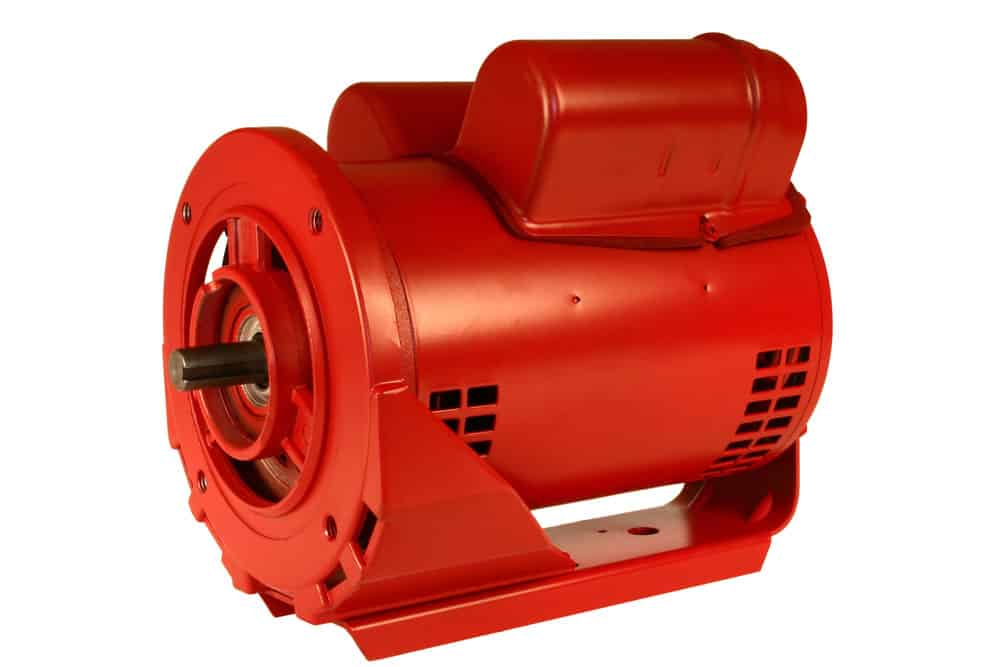
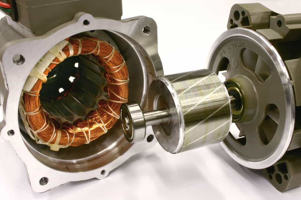
Motor Wire

The motor and main wires differ because the motor wire’s insulation has more delicate strands of copper. They usually can withstand up to 600 volts and temperatures as high as 2210F. Also, it can withstand higher voltages without any complications. 

TXL, GXL, SXL Wire

Wires made of single-stranded conductor type of copper are usually TXL. These wires have cross-linked polythene to insulate them.  GXL wire is a single-conductor primary wire with XLPE insulation. SXL wire, on the other hand, has a bare copper conductor and is protected with XLPE. 

The jacket made of cross-linked polyethylene means the wires have better aging, abrasion, and heat resistance.

Further, depending on the application area, the insulation thickness differs. The TXL wire differs from the other two types because it has thinner insulation.  And GXL wires are a cross between SXL and TXL wires in terms of thickness.

Due to its extra durability, the SXL wire is preferred for more intense conditions such as industrial or racing vehicles. However, TXL wires are also used in racing vehicles because they are lighter, helping save on weight.
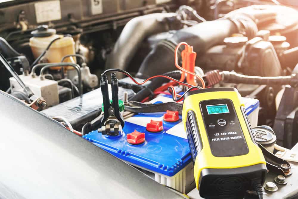
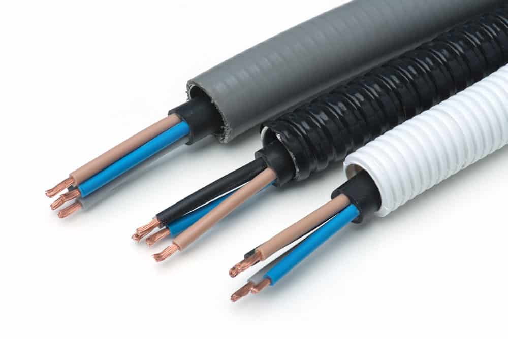
Battery Cable

The battery harness cable connects the battery to the ground and the electrical system. Often it’s thicker in size than most wires.

Speaker Wire

You’ll need speaker wires to transmit audio signals from the stereo receiver to the speakers. Typically, speaker wires serve low voltage purposes. To ensure the speaker sounds right, properly connect the negative and positive terminals of the wire.

Trailer Wire

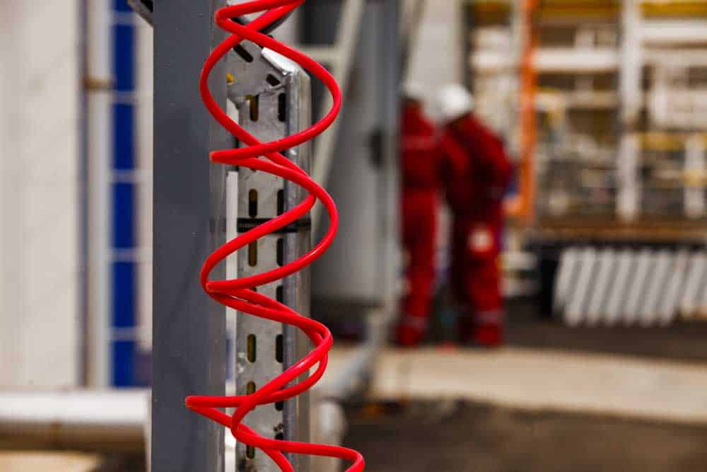
It refers to the primary wire that’s been tailored and colored to serve as a trailer wire. Often trailer wires utilize a color code of brown, green, white, and yellow.

Colorful wires

Colorful wires

Difference Between a House Wire and Automotive Wire

Automotive wires are often used in harsh environments of your vehicle. For instance, they’re used in the engine where if house wires were in the application, they could easily get damaged upon coming into contact with battery acid. 

In contrast, automotive wires can withstand high temperatures and chemical corrosion. Also, automotive Wiring is a more robust and secure jacket while maintaining more flexibility than house wires.

A common mistake many people make is opting for house wires to serve automotive purposes simply because they’re cheaper. Even if the housing wire you picked fits the ideal current carrying capacity, several other factors remain to consider. 
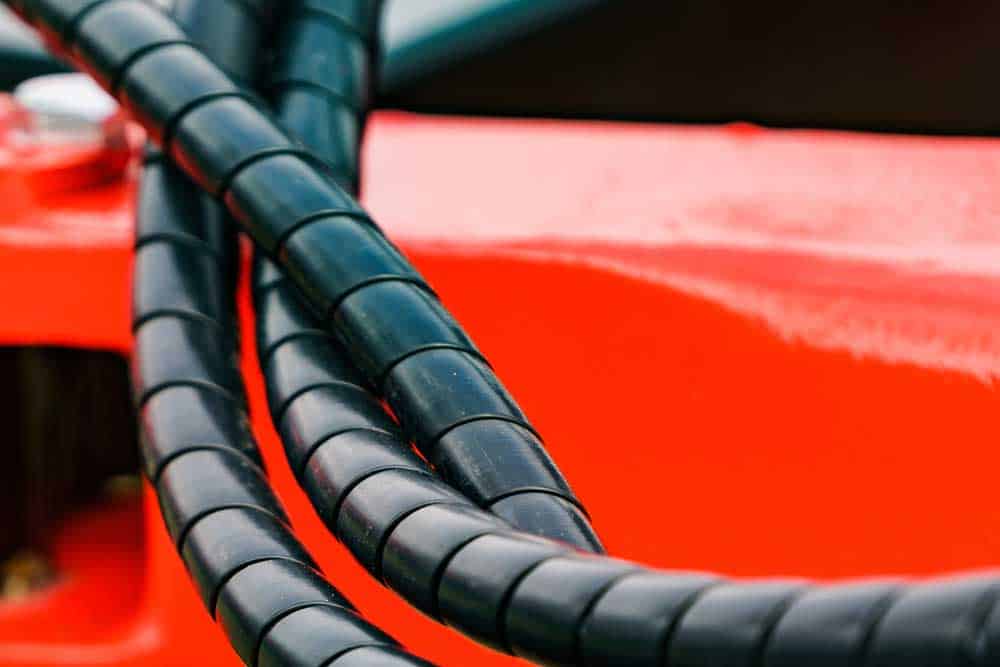
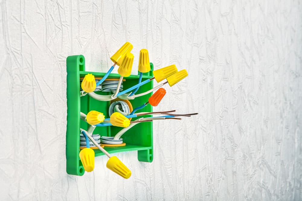
Automotive Wiring Harness Wire:  Wire conduits 

Wire conduits 

Common Vehicle Wire Damages

Due to some reasons, your automotive Wiring suffers a lot from:
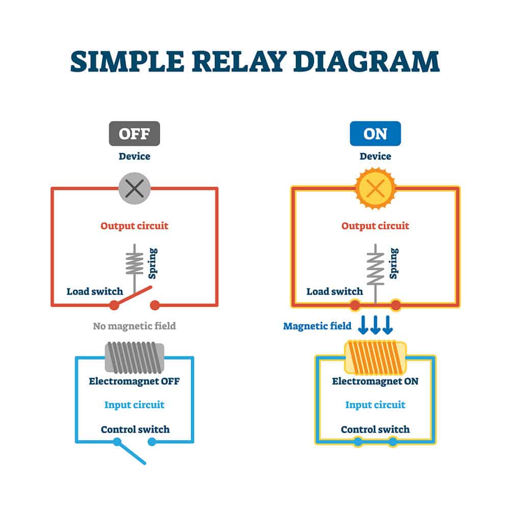
Short Circuit

If the Wiring to the ground or electrical power source is short, it will cause some components in the circuit to malfunction or perform partially. However, it depends on where the Wiring is lacking and how fast it is. 

Open Circuit

If any wire in your system is cut, no current can move from one end of the circuit to the other. Such instances result in an open course.

High Resistance

High resistance can block the current flow, resulting in some of the circuit’s electrical components malfunctioning. The High resistance is often caused by improperly connected Wiring or rusted wires and components.

Automotive Wiring Harness Wire: 
 Interior wiring 

Interior wiring 

What Are the Signs Your Car Has Damaged Wiring?

Wires have conduits that allow the safe passage of electricity along various circuit parts. In case of a wire malfunction, your vehicle will display some signs in correspondence to the connected electrical device.

Malfunctioning of Vehicle Electrical Components

Faulty Wiring could result in several electrical issues, such as a broken radio or lights.

Fuse Keeps Blowing

A fuse is designed to blow if excess volts of electricity pass through a given circuit. If your vehicle has a shorted wire, it could result in excess electricity flowing through a course, which will trigger the fuse to blow.

Car Won’t Start

It’s common for your vehicle to exhibit some issues starting if there are any wiring issues. The problems range from PCM ground wire corroded to a damaged wire in the starting circuit.

Automotive Wiring Harness Wire: 
 Engine wiring harness

Engine wiring harness

How to Choose Vehicle Wires

When picking a wire for your project, some factors should help you make the best decision.

Wire Size

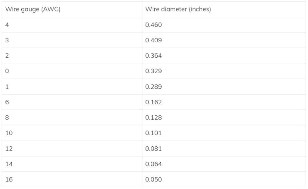
Wires are measured according to their gauge size. However, the gauge scale is inverted, with the thicker wires having a smaller gauge size. For instance, a 10-gauge wire is more comprehensive than a 20-gauge one. 

The amount of current drawn from the circuit and wire length between the electric power source and the course will guide you in picking the correct gauge size to serve your needs better and ensure complete Wiring.

However, if your intended use is doing repairs, ensure you have the technical manuals for vehicles to avoid making costly mistakes. The manual will help guide you as it will likely always have the exact gauge size required for specific automotive components. 

Wire Amperage

Amps determine the total amount of electricity a wire can allow to flow through. 

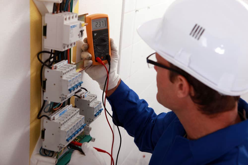
Before purchasing any electrical wires, carefully check the label to determine the current rating. Overloading a wire is dangerous and could lead to shorting out, damage to essential systems, stalling equipment, or in some extreme cases, it could spark a fire. It’s advisable always to ensure you have the right amp rating before buying any wires.

Ensure you know the relays, circuits, breakers, fuses, and any other form of overload protection your wiring project needs. In addition, have suitable automotive wiring connectors for the job. Excess amps will likely short out your connectors.

Wire Materials: Copper or Aluminum

Electrical cables and automotive wire materials are mainly available in two forms; aluminum and copper. Copper wires are often the right choice for automotive wire harness applications. Copper wires are more flexible and conductive compared to aluminum. Also, copper wires are less likely to corrode.

Aluminum wires, on the other hand, are considered lighter and cheaper. However, they are less durable and more susceptible to corrosion. Also, over time, aluminum wires are likely to develop electrical resistance

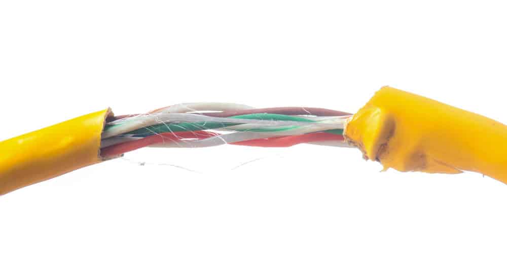
Wire Core: Stranded or Solid

Solid wire is mainly suitable for the wiring harness industry and home use. It’s best to avoid using reliable cables in your car’s Wiring unless you plan on using them to bail wires. With automotive Wiring, you should opt for flexible Wiring. Stranded wire is more flexible since solid core wires can’t bend over and over.

Insulation: Cross-Linked or PVC

To create PVC insulation, first, heat the PVC. Then there’s a die on the stranding through which the PVC is extruded. The insulation is then added via melting through a heat source, which could change the form. There are three main categories of PVC automotive wires:

GPT: Rated 80 °C and suitable for common types of circuit wiring.

HDT: Also rated 80 °C and used as automotive wire for heavy walls.

TWP: Rated 105 °C and used primarily as a thin wall automotive wire. It’s also considered lead-free.

To create cross-linked insulation, first, you’ll use a tube to extrude the polyethylene while keeping it under high pressure and heat. This will cross-link the molecules to another state. Compared to PVC automotive wires, automotive cross-link wires can withstand far higher temperatures, better serving the wiring harness industry. The three most widely used cross-linked automotive cables include:

GXL: Rated 125 °C, considered thin wall, and suitable to work with typical automotive types of connectors.

SXL: Rated 125 °C and considered a standard wall.

TXL: Also rated 125 °C, considered fragile wall and best suited for application on wire harnesses requiring small size and minimal weight.

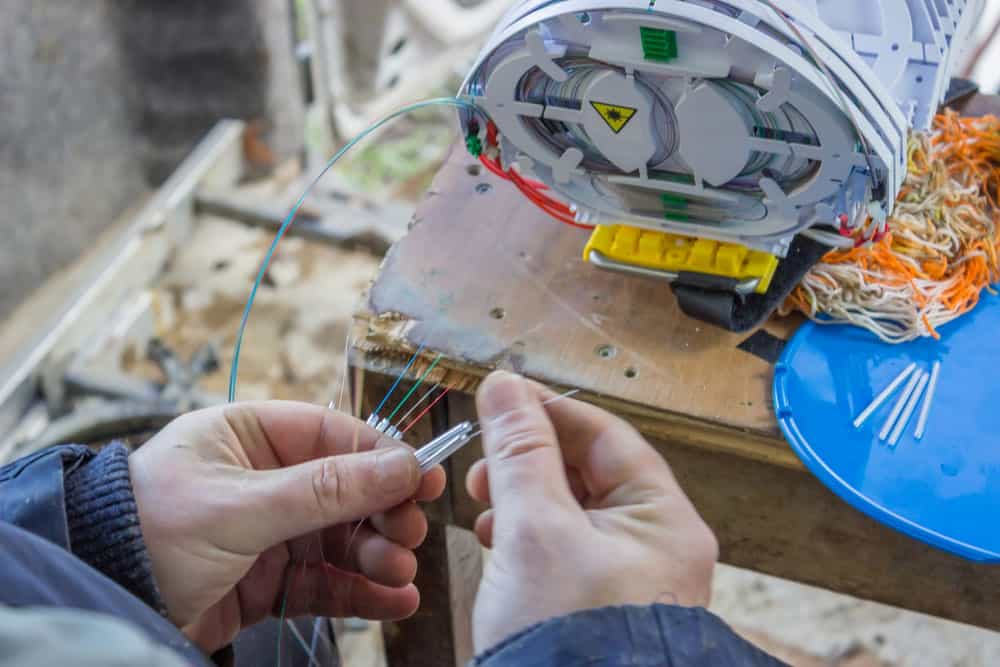
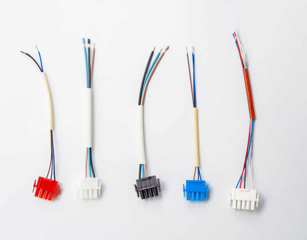
Wire Coloring, Striping, and Printing

Automotive wires are available in a variety of colors. A more straightforward way to organize the necessary cables to accomplish a task or repair is to assign colors to the wires according to the intended use.

You can use colors to identify and track wires back to their circuit. Today, various market sectors have their standard wire color system. Furthermore, you can expand the color scheme by adding a color stripe. 

You could purchase wires with printed wording indicating their exact use for further clarity. Quickly sorting your wires allows you to conduct repairs and efficient constructions efficiently. You’ll develop a color code for future custom wire stripping tasks, saving time.
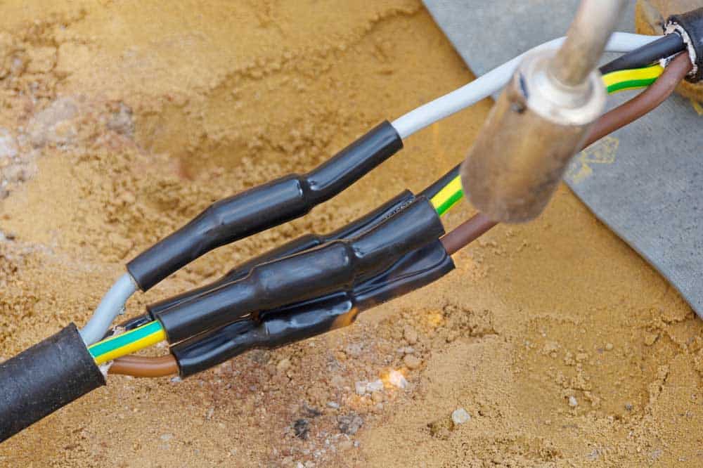
Connections

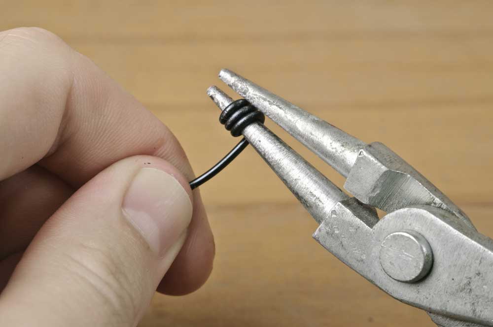
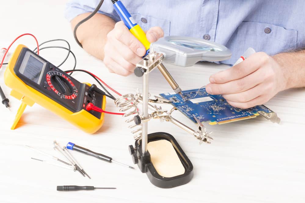
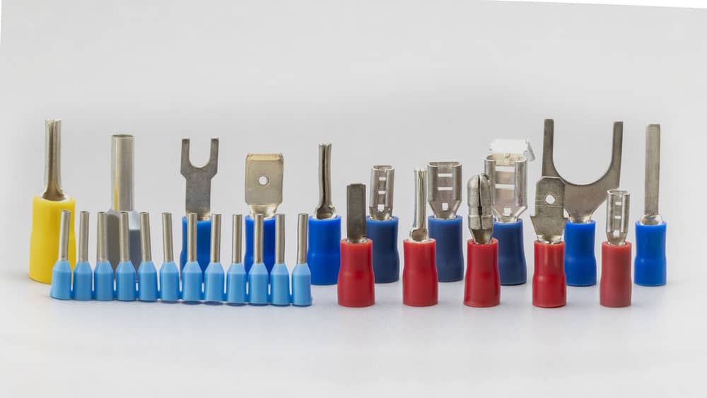
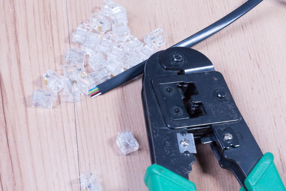
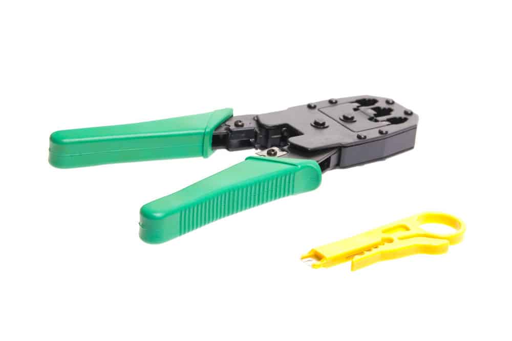
Generally, Wiring uses two types of automotive wire connections; solderless and soldered.

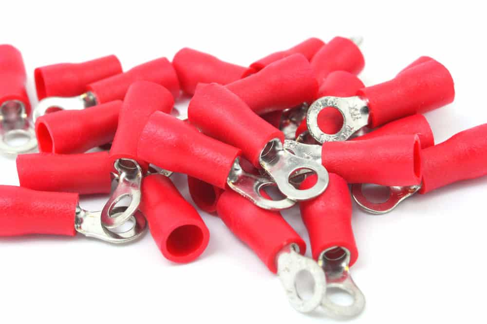
Often, solderless connections are considered the quickest and easiest way to terminate wires. Solderless bonds involve readily available automotive wiring connections such as ring terminals, spade terminals, and quick disconnects. 

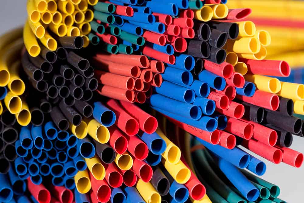
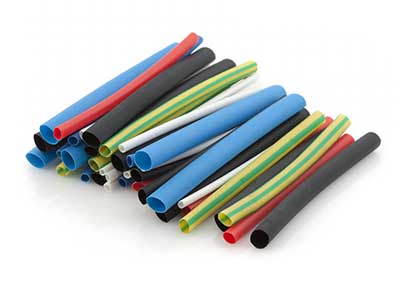
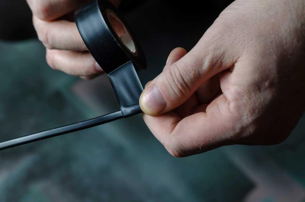
To properly use the following equipment, it’s advisable to learn how to make a proper crimp. Unfortunately, solderless connections aren’t always as long-lasting as the ones you’d wish. However, you could use additional strain relief equipment, such as auto wiring harness tape or heat shrink tubing, to increase the lifespan of solderless connections.

On the other hand, soldered connections are more susceptible to error and difficult to install. With the wide variety of solderless links to pick from, it’s rare to find people using soldered connections. Many professionals today discourage soldered associations because it makes it harder to control quality during the process. 
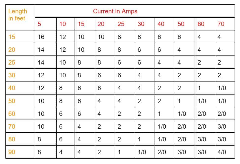
Wire Length

Wire length chart by amps and wire gauge.

Automotive Wiring Harness Wire:  Wire length chart by amps and wire gauge.

Conclusion

There are different types of automotive wiring harness wires, each with other properties. Wiringo is one of the leading wiring harness wire manufacturers, serving automotive companies. Any signs of wiring damage? Look to us for help.

Automated Cable Assembly: Ultimate Guide on Automatic Wire Harness Manufacturing

Coax cable

Wire harness assembly is a manual and time-sensitive process that frequently ends in high costs and a lack of product quality consistency. Also, the project production time could take weeks, depending on cable types and quantities. However, more and more manufacturers are lately using automated cable assembly processes. These have proven to reduce project time spans significantly and be cost-effective.

Wire Harness Manufacturing

Granted, we are unable to transform to complete automation for specific processes. But we can still automate many of the crucial functions.

Processes That Can’t Be Automated

  • Wire Harness Assembly: This is a step-by-step process that must be done manually.
  • Terminal wire installation
  • Removing wires and cables via sleeves and conduits
  • Multiple crimping of individual wires where you’ll pass more than one wire through a single terminal
  • Taping harnesses at the branch after using fabric
  • Binding or harnessing components with loose clamps or cable ties

Processes That Can Be Automated

  • Cutting and stripping wires during the wire harness assembly
  • Crimping terminals on the sides of wires 
  • Plugging of wires that have terminals into connector housings
  • Soldering wire ends
  • Testing for electrical functionality
Heat shrinking tubing

Caption: Heat shrinking tubing

Cable Assembly Equipment and Automatic Wire Harness Machine

Below are some automatic wire harness machines:

AutoStrip 7400

The AutoStrip 7400 wire processing machine is for any strip length. It has a maximum strip length of 1200 and can cut and strip wires at a rate of 500 pieces per hour. If your project requires shorter strip lengths, the AutoStrip 7400 can do the task at a faster speed of 8200 pieces per hour. 

This device can handle gauges of up to 8.66mm. Furthermore, it can take a multi-conductor and flat cable gauge of around 8mm.

AMP-O-ELECTRIC G II+ Terminating Machine

The G II+ is a vital machine the production department uses to process gauges of increased diameter (16mm). It offers precision variable speeds, allowing technicians the flexibility to handle any custom wire harness application. 

Additional features include split cycle operation, a toolless applicator, and manual crimp height adjustment. 

Branson 2000 Xt Ultrasonic Welder

The Branson 2000 Xt Ultrasonic Welder can handle any welding process requiring precision. The device features advanced digital amplitude control to ensure consistency. It also features a comprehensive range splicing system that takes diameters between 0.35 to 32mm. 

In addition, the designs are stacked vertically to prevent side slicing, a common issue in the industry. 

Branson 2032S Wire Splicer

The Brabson 2032S wire splicer can handle any custom harness design process requiring an ultrasonic splicing system. The machine allows the automation of welding operations via ground detection, peak power, or time. 

In addition, the device features programmable starting ramp time, digital autotune, and precise digital amplitude control with proofing to enable complete automation of wire harness production. 

Additional Production Tools and Equipment

A wide variety of hand tools are necessary for semi-automation.

Open wire

Caption: Open wire

Benefits of Automated Cable Assembly 

Some benefits of automated cable assembly include:

Make Up for Downsides of Manual Processing

While machines can malfunction, there’s always a margin of error accompanied by manual production. Often these errors are related to incorrect wiring systems and damaged pins and connections.

In contrast, once programmed, machines are less prone to errors and don’t get tired, bored, or distracted from repetitive tasks. 

Also, their levels of output and efficiency are much higher. For example, instead of employing traditional visualization, you can save up to 70 percent of the time with automated wire assembly.

Make Sure Product Uniformity

Wire harness manufacturing processes like balanced terminal pressure and precise stripping ensure continual quality and product uniformity, which means consistency and shorter production time. 

Control Quality

Optimizing quality control in manufacturing components with automated cutting, stripping, and crimping machines are more accessible. These processes also follow exact specifications. 

For example, automated systems enable monitoring of sealing, crimp force, wire end, and knots in components, as well as separating the good from the bad. Also, when fully automated, crimping machines can provide processing options and twist and turn wires to varied lengths and cross sections.

Increase Production Run Capacity

Both high-mix, low volume requiring quick changeover capability or high-volume production of wire harnesses requires automating the cutting, stripping, and crimping machines.  

Automating these machines also helps maintain consistency, efficiency, and quality. The result is optimized quality control, higher output and efficiency, and reliable wire and cable components. 

Embrace the 4.0 manufacturing philosophy

New-generation wire harness design software employs advanced tools. Such tools are not only automated for today’s options. They’re built for compatibility with future manufacturing solutions.

Automated Wire Harness Assembly Processing at Wiringo

Below are some of our capabilities in automated wire harness assembly processing, showcasing our expertise and precision in delivering high-quality solutions.

Equipment

At Wiringo, to satisfy customer needs, we have incorporated the use of state-of-the-art designs in the cable and wire processing industry, such as:

  • Crimping/Presses/Applicators
  • Circuit Analyzers
  • Heat Shrink Applications
  • Terminators/Automated Termination Equipment
  • Overmolding Equipment
  • Ultrasonic Welding
  • Automated Testing
  • Wire Stripping Equipment
  • Laser Marking and Kitting

Services

We can provide you with:

Machine Precision Wire Preparation

We utilize automated machines and benchtop equipment to cut, strip, and terminate coax, ribbon, and jacketed cables. We are capable of processing wires between 30 AWG and 40 AWG. With the help of our automated machines, we can work at rates of up to 10,000 wires per hour. 

Crimping

Seeing that terminal crimping of wires is a core production process, we assure you that we have the experience and proper equipment to handle the job. We use hand tools, benchtop presses, automatic processing machines, and pneumatic and hydraulic presses to manage any tasks.

Wire Marking

For all your wire marking needs, we provide the following services:

  • Heat shrink labels
  • Hand-placed vinyl labels
  • Direct inkjet printing
  • Machine-wrapped vinyl labels

Wire Bundling

To securely bundle wires, we utilize tie wraps manually or via semi-automated machines.

In addition, we are fully stocked with a wide array of shrink tubing sizes, styles, and colors. We can shrink the tubing using a heat gun or a calibrated oven.

Also, we use cutting-edge equipment to perform precise and uniform wire twisting. In addition, wires are retained in the twister by softly gripping the cables inside the pressurized surgical tubing. 

Soldering/Tinning

At Wiringo, you can rest assured because we can handle all your soldering tasks, from PC boards to through-hole devices. 

Beading

Beading is the wrapping of wires on a component or device. For most jobs, ferrite beads are used.

Custom Harnessing

We fully utilize our cable and wire harnessing techniques from crimping to bundling to design any complex wiring harness. 

Testing

Before any project, we always ensure to perform a complete electrical continuity test. The test helps ensure there are no opens, shorts, or incorrect wiring.

Conclusion

Automation of wire harness processes enables manufacturers to increase productivity, maintain quality, and improve efficiency, satisfying all your needs. At Wiringo, we pride ourselves on the wiring harness and cable assembly industry. We are constantly upgrading our computerized systems to enable the real-time cable assembly process. 

Automotive Wire Harness Protection: The Ultimate Guide

Heat shrink tubes

Vehicles have numerous systems, all of which rely on proper wiring. The wiring regulates power, receives signals from the ECU to control components, and stores data that ensures the car runs smoothly. And the more systems the vehicle has, the more wiring is required. 

Engines are designed to run continuously at very high temperatures of over 2000F, to which the wires are constantly exposed. A lack of proper wire insulation would damage the wiring, which could potentially cause a short circuit igniting an electrical fire. However, overheating is just the beginning of automotive wire harnesses’ problems. The wiring needs noise reduction, thermal protection, electromagnetic shielding, radiant heat protection, abrasion, and mechanical protection. All in all, automotive wire harness protection is necessary.

What Are Wire Harness Protections/Coverings? 

Wire harness protection is the sleeve, wrapping, conduit, tape, or tubing that securely covers and bundles the harness, protecting it from high temperatures and environmental conditions. However, different harnesses require specific characteristics and properties, such as:

Braided Cable Sleeve

Braided cable sleeves are made of mesh to protect your wires. You can singe the sleeve with a hot knife to prevent unraveling at the edges.

You could opt for expandable sleeves made of polyester that provide an open-end weave construction, allowing for easy installation and reducing installation costs. It protects the wires by allowing moisture and heat to dissipate. Plus, it maintains flexibility even if you bundle a couple of wires together. Expandable also comes in polyphlyne that best suits high-temperature assemblies. Also, polyline has low moisture stability, low wear, and high chemical resistance. 

You can also opt for self-closing braided sleeves that are abrasion resistant and made of polyester. These provide a 25% overturn, hence easy access to the bundle inside. Plus, it can be assembled over already laid wires.

Another sleeve option is the thermal sleeve protection made of Nomex fiber. The fiber is ideal for high-temperature conditions and provides abrasion resistance and thermal protection.

Cable sleeve

Cable sleeve

Cable Wrap

Spiral cable wraps provide cost-effective protection for wires and hoses. They’re flexible, crush resistant, and easy to install. These cables can be branched to provide a simple cable management solution.

Most wraps are made from polyethylene or nylon. Nylon wraps are more heat-resistant because they contain stabilizers that slow down the loss of physical properties as temperatures increase. 

Polythene wraps, on the other hand, provide a more durable cable wrap solution. Plus, polythene wraps maintain their integrity and strength even after being flexed and bent a couple of times.

You could choose between nylon and polythene with hook and loop braided cable wrap. They offer the simplest cable assembly management solution. These cables better serve nonindustrial purposes such as lighting and photography. Also, they can be reused, which could save you a lot. Similarly to spiral wraps, breakouts could happen.

The Cable wrap

Cable Conduit

Cable conduits route and protect wires in machines and structures. The lines have grounding and bonding abilities, helping minimize electromagnetic interference. Pipes also prevent emissions from the power cables they house.

Some conduits are plastic, offering more flexibility and higher fatigue life. Plastic pipes are vital, enabling them to recover quickly after being crushed. They also provide UV resistance, allowing for use in exterior areas. Some of the plastics include:

  • HDPE – Durable, flexible, and chemical resistant. Ideal for telecommunication, power utilities, and trenching.
  • Polypropylene – Offers high flexibility and compression strength. Mainly used in cable assemblies, embedding into walls, and under-floor wiring.
  • Nylon – Protects against abrasion and impact damage. Ideal for vehicle harness protection and hydraulic hose protection
  • PVC coated metal – It’s corrosion resistant and liquid tight. Most used in factory wiring and machine connections.
Conduit image

Caption: Conduit image

Heat Shrink Tubing

Heat shrink tubing involves enclosing cables and wires in plastic tubes. To provide a close tight fitting for the wires and a rope,e you’ll need to shrink the lines using a heat gun or blow torch.

Polyolefin is mainly used to make heat shrinking tubing because of the following reasons:

  • Flexibility
  • Durability
  • Chemical resistance
  • UV resistance
  • Ideal electrical properties

The tubes not only act as cable sleeves but also provide strain relief. Cables and wires often serve a shorter lifespan because of the strain caused by working in limited spaces or being fast. Heat shrinking tuning reduces the stress on your wires and cables enabling them to work effectively. 

With heat-shrinking tubing, you can opt for colors or clear tubing. Colored tubing is ideally used in automotive, cable TV, wireless and telecoms, and electronics, while clear tubing is used primarily for electronics, automotive, and appliances. You could opt for the clear tubing, especially when heat retardancy is a priority, but mechanical performance and electrical insulation are vital.

Heat shrink tubing

Heat shrink tubing

Tape

Taping is a tiresome task. Although tape might not be the best solution due to its high cost, it takes up little space and is easy to install. The tape is wound around the wires in a spiral form to cover the areas between sleeves and other solutions.

Taping

Taping

How to Select Cable Protection for Automotive Applications

When choosing protection for your automotive’s wire harness, there are several factors to consider, including:  

 Sealed or Open System

When choosing cable protection for automotive purposes, the main factor is whether the cables can operate efficiently and reliably with zero to minimal protection.

Automotive split walls are highly flexible and light. Therefore, they tend to peel open when exposed to frequent vibration or excess flexing. 

When that happens, it lets in water and debris, which make their way to the harness, causing wear and, over time, damage. Hence the need to cover automotive looms with tape to seal off the conduit and help avoid such problems. 

However, taping the automotive looms demands extra work. A lot of labor goes into the building process, consequently increasing the overall costs and reducing the functionality of the harness. And since automotive looms are made of lightweight materials, they don’t offer adequate protection on expensive vehicle harnesses.

Cable protection systems like the IP66 and IP68/69K protect the cable from splashing and high-pressure washdowns, keeping the harness clean and safe from quick wearing off and failure. 

Sealed polyamide protection systems are more robust and serve longer than taped automotive looms. Polyamide also offers a wide selection of materials with numerous features and different flammability ratings, allowing you to make the best choice according to the intended use.

Location of Harness

When the harness is close to the transmission, engine, or catalytic converter, it requires high-temperature polyamide protection. 

There’s a wide variety of products with temperature ratings ranging between -400C to 1150C and products that can handle temperatures of up to 3000C. 

You don’t have to use solid materials if the harness is inside the vehicle. However, a retrofittable and divisible conduit system could prove beneficial, enhancing the ease of adding wires for add-on features like lighting and WiFi.

Material Selection

Light and medium wall products are sufficient if the components are not exposed to harsh conditions or rough handling. But if they will be exposed to extreme conditions, it’s better to go with the heavy wall polyamide cable protection made of material with the following qualities:

  • High impact and can resist high temperatures
  • Increased flexibility to continuous motion, such as in the robotics field
  • Low toxicity performance in passenger areas that complies with the Bombardier and ASTM standards
  • UL94 V-0 compliance for low smoke

Robust polyamide cable protection systems also offer increased flexibility and high impact resistance, vital in applications involving jumper cables linking automation, such as subway cars. 

The protection system should also have an increased diameter to protect large bundles of cables. In addition, the capability to be retrofitted and divided to allow adding or removing of wires during the vehicle’s service life or while building the prototype.

Cable Protection System Accessories

The best cable protection system supports the conduit, ensuring efficient and effective installation. There are several accessories to enhance performance, including:

  • Y and T junction fittings
  • Divisible lock nuts
  • Fittings with inbuilt strain relief
  • End sleeves
  • Clamps
  • Abrasion rings
  • Divisible fittings for retrofit applications
Image of Clamps

Image of Clamps

For heat shrink tubes

  1. Whether to opt for a single wall or dual wall heat shrink. Although the single fence is widely used, the double wall (adhesive lined tubing) has a better connection and more robust seal, among other advantages. The following are factors to consider when choosing heat shrink tubes: 
  2. The tube’s shrink ratio. The heat shrink ratio differs from the initial heat shrink tube size to its skeletal form. The difference is a ratio of 2:1 to 4:1. Typically, the heat shrink tube decreases the size by 50% to 75% once some heat is introduced.
  3. Lastly, it’s essential to consider the heat-shrinking tube size.

6 Types of Cable Wrap for Automotive Wiring Harnesses

Below are six cable wrap options, depending on the auto wire harness’s physical properties and electrical performance.

Corrugated Flexible Conduit From PE, PA, or PP

While the car is running, the engine gets exposed to high temperatures. Therefore, the PP plastic wrap for the engine is a unique material with a high flame redundancy and light-off to prevent sparking a fire.

PP wrap has a high melting point, making it the perfect wrapping material. Even when the engine is under extreme temperatures, it’s less likely to result in a fire. 

In addition, PP corrugated tubes have a low thermal conductivity. Therefore, even if the engine temperatures are high, it won’t affect the expected operations of the neighboring components.

Self-Closing Non-expandable Sleeving From Polyester Monofilament and Multifilament

This open-type design is easier to install and remove. Also, it has high wear resistance, providing excellent protection for the harness during bending activity.

Braided Self-Closed Wrap From PET Monofilament

This wrap has a self-rolling coincidence of around 25% and combines flame redundancy and wear resistance to provide protection. It also has a high-temperature component peripheral guard.

Dual Wall Adhesive Heat Shrink Tubing From Polyethylene

This tubing comprises an outer polythene layer and an inner layer of hot melt adhesive. It fits closely on wires, smoothing rough edges and providing electrical and thermal insulation. 

The adhesive tubing ensures a tight seal against moisture and chemicals that could corrode the harness. However, it’s challenging to apply and requires a heat gun, which increases production time.

Cable Expandable Sleeving From Polyester Monofilament

This sleeving is often used to cover wire harness tubes, industrial hoses, and cables. It can maintain complete flexibility in any direction, regardless of low temperatures. Also, it allows for repeated flexing of cable assemblies and wire bundles without causing damage.

Fiberglass Braided Sleeve

The fiberglass braided sleeve has a temperature classification of about 2000C and self-extinguishing capabilities. In addition, it has a high voltage resistance and a wide temperature range. It’s widely used in motor peripherals and generators.

Conclusion

Harnesses must ensure smooth transmission of signals and connection of circuits. You need a properly calibrated and reliable system to prevent electromagnetic interference on circuits and eradicate short courses. Thankfully, a wide selection of components is available, so you can choose one that better serves your needs.

Wiringo provides all wire covering and cable protection services, from heat shrink wrapping to expandable tubing. Our team of experts is always ready and equipped to handle all your requirements in all applications.

Curly cord: An Ultimate Guide on Curly Cables

Curly cord in Telephones

When your phone is ringing, you grab it off its stand and drag it towards you. Here, curly cords ensure that the wire does not bounce right back after you go to the end of the line. And the handset’s coiling cords neatly retract into the base when it’s put back. The cable’s expansion is due to the presence of coiled conductors. Without it, you’d have a huge mess of wires behind your telephone. So, how important is the curly cord?

Curly Cords Basics

You can get a curly cord everywhere, from a car charger for your phone to a cheap key chain at the corner store. One widespread application is the telephone, which uses curly cords to connect the handset to the base unit. “Curly cords” connect two devices when one or both need to move relative to the other.

Besides their more common names, curly cords can also be referred to as:

  • Coiled Cable
  • Coiled Cord
  • Spiral Cable
  • Retractable Cable
  • Coil Cable Retractile
  • Retractile cord
  • coil cords

These power cords get their names because they go back into a tight coil. 

Wire around a plier

Caption: Wire around a plier

Two Basic Categories of Curly Cords

There are two kinds of curly cables, mainly cycled and stationery.

Cycled curly cords

The first group, or cycled one is for medical devices. It is because you have to use them many times and can’t fail at all; hence, they are built differently. So, the process for making stationary curly cords is very different from the process for making reliable curly cords.

Stationery curly cords

As for the stationary one, these curly cords can stretch only once. It means you can use them when one of your devices is in a fixed position while the other keeps moving away. Moreover, you cannot go back and forth with stationary cords. Instead, you will always use them to connect a stationary and a moving device. These kinds of coiled cords would be made for a purpose that keeps them mostly still.

Silver gray curly cords

Caption: Silver gray curly cords

Spiral cables penetrate many industries.

You can find the curly cords just about anywhere. 

Medical setting

As mentioned above, medical devices need curly cords for convenience.

Electronics industry

The two most popular locations are the house and the car. For example, the convenience of your phones would not be there if spiral cables were not present. So is the phone car charger.

Telecommunications business

Spiral cables join cell phone connectors and the cigarette lighter adaptor plugs that power them in cars. Also, you will look for everything from GPS to radar detectors and cooling systems that you attach to a car’s cigarette adaptor.

Retails

Additionally, curly cords prevent the theft of high-priced merchandise from store displays. It tethers the products so that customers may drag them only a short distance before the wire snaps. Hence, the retail sector joins the ranks of those that place a premium on spiral cables, such as the cellular phone sector, the public safety sector, the medical sector, and the GPS/radar detection sectors.

Automobile industry

You may have seen the curly cord in every car production plant that employs robotics and power tools.

Building industry

On the highway, if you come across a construction site, you’ll likely find spiral wires linking GPS units to tiny computers on the machinery used to move or pave the earth. They communicate the data such as elevation data, dirt and concrete volume, and other construction site metrics. Moreover, it allows you to observe the procedure from afar. Thus, curly cords with many turns enable this entire system. 

The benefits of the Curly Cord

  • Mobility – As mentioned in the phone example above, spiral cables can be readily bent and moved to access areas that normal wires can’t. Hence, more freedom at work through mobility equals more output.
  • Durability – Spiral cables are often thicker than ordinary cables, making them more resistant to durability. Because of their thickness, they sustain little harm when gliding over uneven ground.
  • Compatibility – Standard cables take up more room in storage than their spiral counterparts. However, curly cords don’t take up as much room as other wires because of how easily they coil up.

There are some benefits and cons to using spiral cables. Though they are lighter than standard cables and can help you save space, they are heavier. The cable might cause injury to nearby objects or people if you stretch it too far and then retract it improperly.

Spiral electrical wire at the construction site

Caption: Spiral electrical wire at the construction site

Specifications of Curly Cords

The following is what must be taken into account when you are choosing a curly cord.

Cores and Conductor size

Spiral Cables are available from 2 to 25 cores with conductor sizes as little as 0.14mm2 up to 6mm2.

Screen

To accommodate the spiral’s expansion, you will use a lapped screen. In such cases, foiled screens are not a good choice.

Material and Color

  • PVC is inexpensive to produce but has a poor memory; it recoils back after some uses. The range of available colors in these is typically greater. PVC cables have a 3.5x length-to-size ratio when extended.
  • PUR is highly flexible and has excellent memory. Moreover, it resists most oils. If it were black, it would also be UV stable and resistant to the effects of water. Though typically black, you can also find them in white, yellow, and orange. PUR cables have a 4-to-1 stretch-to-retract ratio, making them extremely versatile.
  • Rubber is useful in manufacturing settings. Comparatively speaking, it has a greater memory than PVC but is not as good as PUR. It would be impervious to moisture and sunlight. Rubber cables can extend to five times their original length, and usually, they are available in black color.

Retracted length/ Extended length

When retracting, the length of the curly cords is the same as its available length (not stretched out). Here you can stretch it to a maximum of 5m. When you extend it to the farthest, it is the extended length.

When calculating these dimensions, you must additionally account for the cable’s aspect ratio.

  • PVC – 3.5:1
  • PUR – 4:1
  • Rubber Band – 5:1

What type of tails/ What length of tails

The straight ends of any curly cable are known as “tails.” Moreover, these can vary in terms of both length and direction. Two of these directions are the Right angle (or tangent) and axial (or straight).

DIY Coiled Wire

DIY coiling stranded wires are simple and can be done with any vinyl covering the wire. Using a heat gun and basic tricks in less than 10 minutes, you can transform any straight stranded wire into a spiral one.

Now, you will wonder why stranded wires and not solid ones. The answer is simple; as stranded 

wires are more flexible, they can curl without breaking the core conductor. On the other hand, the solid wire has one single core that does not accept bending and can break.

So let’s see what you will need to have on your hand.

Material Needed

  • Dowel or stick around which you will form a coil
  • Electrical Drill
  • Cable Cutters
  • Heat Gun
  • Pliers

Method

  • Secure one end of the wire on the dowel with the help of tape. Later, you can cut the straight end or join the plug with it.
  • Start wrapping the wire from the fixed end tightly on the dowel stick. Keep pushing the winds next to each other as you proceed further. Moreover, you can do the work either clockwise or anti-clockwise.
  • At the end of wrapping, secure the other end of the wire on the dowel with the help of tape.
  • As the wrapping is done, you will now heat it using a blow dryer or heat gun. Now, you don’t want to melt the sheathing, so you need to maintain a good distance from the wire. Also, uniformly distribute the heat by the constant movement of the gun.
  • After a few minutes, you will see that the jacket is becoming shiny. It has now become a spiral and accepted its new shape. Let the wire cool down, and then remove it from the stick.
  • In the end, inspect the wire for any scratches and burning signs. That way, you can ensure that the quality of the wire is not compromised and is ready to go.
  • And there you have it; your DIY coiled wire.
Spiral wire 3D illustration

Caption: Spiral wire 3D illustration

What to Consider When Designing Specific Curly Cords 

If you are an OEM searching for a long-lasting coiled cord solution, we advise you to consider several factors before placing an order with a supplier.

You should first consider the setting in which you will be using the cables. Designing a curly cord for an industrial setting differs from designing one for a medical or retail setting.

Then, determine the lifespan and level of activity you desire for your ringlets. If, for some reason, you need coiled cords with a lifespan of 100,000 cycles, you’ll want to make sure those requirements are baked into the design from the start.

Another example would be if you needed your curling cords that will last forever and be put through 30 washes a day, you’d want to be sure your supplier could accomplish that. In one extreme case, a coiled cord must withstand 500 motions daily for an entire month (15,000 cycles total).

Conclusion

Curly cords are important in places where you need durability and mobility. While compacting the wire’s length, they do not break when pulled extensively. There are different conductors diameters from which you can choose the cord. After determining the conductor diameter and number of cores, you must select the insulation and sheathing materials best suited to the application. Custom orders for the spiral’s retracted length are possible up to 5 meters in length. Moreover, you can make it at home with simple stranded wires and use it for your next wire harness project. Here at Wiringo, we offer any wiring harnesses and cable assemblies to make your connection safe and reliable.

How To Wire A Harness: An Ultimate Guide on Automotive Harness Wiring

How To Wire A Harness

How To Wire A Harness?

When you get a factory harness for your vehicle, you will get all the wiring essential for all the standard electrical components such as headlights, horns, windshield wipers, etc.

However, you sometimes want to add more electrical components to your vehicles, such as racing electronics or high-end audio.

If you want your systems to work at their full potential, you need to learn a few tips related to making the wiring of a harness easier and more effective.

Round up the right tools

The wiring job becomes much more manageable if you pick the right tools. 

First of all, take good quality wire strippers. Mostly, wire strippers have several holes that can fit different wire gauges.

The wire strippers help strip the insulation off the wires properly without damaging the conductors inside. 

The second tool that you may require is a wire crimper. You can install solderless connectors with a wire crimper.

If you choose a quality crimper, it will have two-three sections on its nose to fit into various lug sizes.

Additionally, there are crimpers with wire cutting and wire stripping sections. 

Some connectors are difficult to crimp; thus, you need a soldering iron to splice and secure such oversized connectors.

Several solder types are designed specifically for electronic products and electric wiring.

They have active resin core flux, which cleans the wires on heating.

As a result, it removes any extra oxidation or corrosion on the wires.

When cleaned, you can solder the wires with lesser heat, making the connections strong and having less electrical resistance. 

Other than these basic tools, you should also have these items in your electrical toolbox:

  • A wire brush so that you can remove grease, oil, or heavy corrosion before soldering.
  • A voltmeter and an ohmmeter measure the circuits’ voltage and resistance levels.
  • A test light with which you can check the power in the circuit.
  • Shrink tubing materials for insulating connections from outer elements. You can insert this tube over the connector or the solder joint, which shrinks permanently on heating. 
soldering iron

soldering iron

Gauge your wiring needs

While choosing wires for electrical systems, you must consider three essential factors.

Size: You measure the wire size with its gauge. As the gauge becomes heavier, the wire becomes smaller, and vice versa.

Now, how will you decide on the wire gauge? You can choose it based on the current drawn in the accessory and the length of the wire between the power source and the accessory.

If the current in the accessory is high, you must take heavier gauge wires.

Caption: Wire Gauge to Wire Diameter Comparison Chart

However, when the wire is of longer lengths, you may face the issue of voltage drop.

But you can offset this drop by increasing its size. As a thumb rule, you should try to get less than a .5% of voltage drop to ensure the highest performance.

Wire materials: Generally, the wires are made from aluminum or copper. If you choose wires for automotive applications, you must take copper wire for higher flexibility and conductivity. 

Wire color: It becomes essential when you have to find out about any faulty wire.

Thus, it is always better to color-code all the wires based on the accessory.

Such marking will help you identify wires during installation and troubleshooting. 

Make the connection

You can take either of the two connectors: soldered and solderless. 

You will need soldered connectors for oversized wiring or splicing the wires together. 

On the other hand, all other wires use solderless or crimp connectors. Solderless connectors are very easy to use and give a powerful connection.

These connectors come with color-coded insulators so that you can know which one to use for which gauge wire.

You can get various configurations in solderless connectors as follows:

  • Butt connectors: These cylindrical connectors are ideal for joining the ends of two wires together. You can insert each wire end into each end of the connector. After inserting, crimp the connection to secure it tightly.
  • Spade connectors: You must use this type of connector for all those components requiring removal or servicing quite often. Here, you connect the male connector at one end of the wire and the female at another. This male and female connector will fit into each other to form the connection. When you want any repairs, you need to pull the wires apart.
  • Ring connectors: You can fix the wires to screw-type terminals with these connectors and secure them with a terminal screw.

Whether you are using soldered or solderless connectors, it is always advisable to use heat shrink tubing to make the connection more secure and safe.

Heat shrink tubing is easy to install and protects against short circuits and other outside components.

Insulated female electrical wire crimps terminal connector.

Insulated female electrical wire crimps terminal connector.

Choose the correct wiring harness components.

When wiring a harness, you should take some overload protection to save your expensive electronics from getting damaged.

There are three main types.

How To Wire A Harness: Fuses

You can connect a fuse to a circuit.

Whenever more power is in a circuit than required, the fuse will blow, thus protecting the circuit from shorts. The fuses come in amperage ratings; the most common ratings are 3,4,5,6,7.5, 10, 12.5, 15, 20, 25, and 30 amperes.

It is advisable to use a fuse slightly higher than the rating of the accessory.

For example, if an electric fan has a rating of 19.5 amps, use a fuse of 25 amps.

How To Wire A Harness: Fusible links

Fusible links are another way of protecting the circuits.

These alloy-made wires have a melting point lower than regular copper wires.

You can splice the link in line with the accessory’s power line.

When there is electrical overloading, this link will melt and thus prevent the electrical power from reaching the accessory.

How To Wire A Harness: Circuit Breakers

The circuit breakers switch off the power to the electronic accessory whenever there is an electrical overload.

Once you restore the correct power, you can reset the circuit breaker.

There are circuit breakers with manual as well as automatic reset options.

They all come in different amperage ratings as fuses.

How To Wire A Harness: Relays

You can also use relays in the wiring of the electrical accessory if they draw higher currents than standard power rates.

As most switches have designs to work with limited currents, you need relays whenever you buy a new electrical accessory from the market.

Relays become more critical when using electrical accessories with high amperes, such as fuel pumps, electric fans, HID headlights, etc.

These accessories activate with an electrical coil and get controlled by a switch.

No power flows to the accessory if the relay is in a close position.

When you turn on the accessory switch, the relay opens and sends power to the concerned accessory.

Apart from these, several other components make your wiring easier, such as 

  • switch panels, 
  • push-button, 
  • toggle, 
  • remote-mount switches, 
  • multi-circuit main and auxiliary fuse blocks, 
  • and wiring harnesses.
How a relay works

How a relay works

Map out a plan

It would help if you always mapped out a plan before you started your wiring project. 

First, lay out the wiring and harnesses to understand the basic wiring scheme and whether you have enough wires to complete the task.

Put the fuse box in an easy-to-reach location, such as in the glove compartment or the center console. 

Now, put all the required relays, circuit breakers, fuses, and fusible links at the wiring connections between your electrical accessory and the power source. 

See if the wiring is labeled.

If not, label all the wires and harnesses according to the name of the electrical components they are routing to.

If any wire goes through the firewall, use a grommet so that sheet metal does not cut the wires.

Secure the connectors only when the wiring has been done through the firewall.

Pick a spot near or on the firewall for the cable harness’s ground point and another point for the chassis ground on the vehicle’s negative side.

With this, you get one path to the negative side of the vehicle and provide a more effective ground point.

Always use a gauge wire of 10 or more to connect the chassis ground to the common ground. 

Keep calm, stay organized, and take sufficient time to understand and manage things to complete harness wiring.

If wiring is done correctly, the installation time of the wire harness assembly process decreases rapidly.

Lay out the wiring harness

Lay out the wiring harness

Conclusion

Complex wiring is like a nervous system for your vehicle.

If not done correctly, one or more electrical accessories may stop working overtime. If you need any support, Cloom technicians are here to help you.

Our knowledgeable and expert team of engineers and technicians can guide you through the entire process.

Also, we manufacture high-quality custom wiring harnesses and cable assemblies for various application requirements. 

Harmonic Study: The Guide to When, Why, and How to Do This Analysis

A waveform illustration

Harmonic currents and voltages can harmonic currents and voltages can have various strengths.

Depending on the electrical setup, the system can handle those levels.

A harmonic study helps you analyze this wave distortion and reveals whether its ranges are acceptable.

That allows you to find potential issues and deal with them.

If you’d like to learn more about harmonic study, we have a detailed guide below!

The Overview of a Harmonic

Harmonic is a type of waveform that occurs in electricity.

The form is non-sinusoidal and occurs periodically. So, how would you present it?

 Sine wave - illustration

Caption: Sine wave – illustration

You would use a sum of the sine wave whose integer is the basic frequency’s multiple.

However, there might be a superposition between the harmonic wave and the basic frequency.

If that occurs, you’ll notice the forming of a distorted wave, and that’s what makes it non-sinusoidal.

How to Produce Harmonics

You need a non-linear load to produce harmonic waves.

That’s because a non-linear load reduces the amount of electrical energy the system utilizes.

So, these loads imply semiconductor components achieve higher efficiency.

While that’s useful, these parts can lead to interference.

That interference appears as current distortion. It also adjusts the voltage signals that go back into the power setup.

If that happens, that means a harmonic occurred.

Here are the most common harmonic sources across various industries.

Electric Devices

A PC desktop can cause harmonic waves

Caption: A PC desktop can cause harmonic waves

A wide range of products can cause harmonic distortions.

That includes the following: 

  • Pumps and fans that have VFDs – variable frequency drives.
  • Personal computers and instruments with SMPS – a switched-mode electricity supply.
  • Harmonic distortion can appear in systems for battery charging.
  • You might face this waveform if you have a flexible AC transmission system.
  • VAR compensators that are static and non-interruptive power supplies can also have harmonics.

Magnetic Gear

The condition is that the equipment is saturable.

For example, this gear can lead to harmonics:

  • Harmonic generators. Synchronous generators create them because the air gap has a flux that distributes in a non-sinusoidal form. You can pick a pitch factor to decrease the harmonics.
  • Transformers. If overexcitement occurs, it might lead to harmonics. If an inrush current occurs, you might notice some waves. However, they only last for a short while.
  • Discharge lamps. Fluorescent lamps and sodium at high pressures can lead to harmonic currents.
  • Rotating machines. Third harmonic currents can appear from induction motors. However, these machines must be under non-standard conditions.

An Analysis of Harmonics’ Effects

A warning sign with graphics

Caption: A warning sign with graphics

Harmonic voltage distortion can cause a wide range of issues.

It has various effects on different parts, including:

  • Capacitors. You’ll find the capacitors and the system has a parallel resonance. That could lead to a shorter conductor lifespan and even its destruction.
  • Conductors. The resistance and current might increase, which leads to cable heating.
  • Neutral conductors. The current can return via these parts. Therefore, you could face overcurrent, heating, and a shorter lifespan of the conductor.
  • Transformers. You might notice too much heat because the harmonics go via windings. Furthermore, that leads to losing thermal insulation and affects overall performance. The torque could be lower, and bearings will deter quickly.
  • Motors. The performance might suffer, and you could face similar issues as in Transformers.
  • Control devices. You can get wrong results and errors. That refers to magnitude values and the zero reference of a wave.

When a Harmonic Study Is Necessary

A person writing down the factors when a harmonic study is necessary

Caption: A person writing down the factors when a harmonic study is necessary

If you are unsure when to do a harmonic study, here are a few pointers:

  • Did you notice a large quantity of non-linear loads? Do a harmonic study if they are above a fourth of the systems or bus’s total load.
  • Is there an issue with power quality?
  • Do the parts of your power system deal with damage frequently?

These are all good reasons for harmonic analysis. You can also do it to meet regulations and check the system’s performance.

What Are the Goals of a Harmonic Study?

Waves oscillating - illustration

Caption: Waves oscillating – illustration

Your goal might depend on the industry. However, the common tasks include:

  • Meeting the Standard 519 of The Institute of Electrical and Electronics Engineers. It’s a document that refers to harmonic control in electric systems.
  • Check how the harmonic distortion affects the system.
  • Suppose you plan to add non-linear loads to expand the system. The harmonic analysis can help to learn how to improve the setup to suit the new needs.
  • Suppose you notice problems that harmonics can cause. Those could include overhearing, devices not working well, etc.
  • That’s part of planning an entirely new power setup.

What Do You Get with a Harmonic Study?

An electrician reading the power output

Caption: An electrician reading the power output

Why would you analyze harmonic generation?

There are many reasons to do a study.

  • Check the existing power setup and collect important data. You can use this data for other tests later.
  • Find where high-harmonic generation appears in your system. Furthermore, learn about its type, place, and size.
  • Check how harmonic conditions affect current and voltage in your setup.
  • If there are any harmonic penetrations, you can learn about them.
  • Find the THD – total harmonic distortion – and its magnitude on each frequency.
  • You’ll learn if the distortion levels align with relevant codes and requirements.
  • Measuring any harmonic indices to ensure they meet the standard is possible.
  • Find if there is any serial or parallel resonance.
  • If you need them, you can create and check harmonic filters.

Harmonic Study and Analysis – Details on How to Perform It

The IEEE developed a guideline when doing harmonic analysis studies.

You can check it to learn more about the process. Here are the major things you should know!

What Tools Do You Need?

Various electrical equipment shown in the photo

Caption: Various electrical equipment shown in the photo

Before you start, you should have the right tools.

If you have a small system, you can go for manual calculations.

However, please note these can lead to errors.

Furthermore, they are often complex. 

You can also try field measurements.

They are useful if you need to check the design or if there is a field issue. If the latter occurs, it can help you diagnose it.

The most common way is a computer simulation.

It’s affordable and simple, but it gives accurate harmonic analysis.

What Data Should You Acquire?

To do a harmonic study, you must get various data first.

Here is what you should have:

  • Gather the system details.
  • The nominal voltage of your bus and limits of harmonic distortions.
  • If there are non-linear loads, what’s the maximum voltage you expect?
  • The short-circuit MVA for the single and three-phase setups. You also need zero, negative, positive, reactance, and resistance sequences (if applicable).
  • Use the basic frequency to get rated voltage, kVa/MVA, and negative reactance. Do this for both the generators and the motors.
  • You’ll need kV ratings of any shunt reactors and capacitors.
  • Resistance and reactance of circuit elements, such as the bus duct and reactors that limit current.
  • The number of pulses, phases, converter connections, and nameplate ratings.
  • The structure and type of the harmonic filter. If there are special buses, make sure to get harmonic limits for each.

Collecting and Preparing Data

An integral step in harmonic analysis is to prepare and model data. It will depend on the system device, but here are some tips:

  • If there is power grid data, ensure the utility is the source.
  • For load data, get it from any tests and the load nameplate.
  • Include test information along with the data from the designer for cable and line data.
  • The manufacturer will deliver data on the rotating machines. Use that info, and details from the factory acceptance test and other checks.
  • Get the info on the transformer and other parts from the nameplate.
  • The manufacturer should get you info on non-linear unit voltage-current features. The same applies to the harmonic filter and current and voltage harmonic spectrum.

If you performed any tests in the above areas, show that data, too.

Step-by-Step Instructions

An illustration of a checklist with the completed first step

Caption: An illustration of a checklist with the completed first step

Do you want to conduct a harmonic study?

The steps are similar for commercial and industrial facilities.

Here are the actions to follow:

  1. You should have a single-line diagram.
  2. Make sure you have the ratings and other info on the gear.
  3. Check where non-linear loads and harmonics appear. Make sure to write down the places.
  4. Call the utility provider and get the PCC’s data and harmonic specifics. Get the lowest and highest fault limits or system impedance that acts as a frequency function in various system conditions. Additionally, get acceptable levels for harmonic distortion.
  5. Analyze the default configuration. You need to find the shunt capacitors and harmonic source bases and find the driving point impedance loci.
  6. Find the total harmonic voltage, as well as the individual one.
  7. Check the ratings with the ones that standards suggest.
  8. If you find something to go above the normal level, make sure to adjust the capacitors.
  9. You’ll need filters in areas where harmonic distortion exceeds the acceptable range.

For the seventh step, here is more information on the adequate ranges:

  • The current should be less or equal to 180% of the rated RMS.
  • KVAR should be less or equal to 135% to its ratings.
  • RMS crest voltage can be less or equal to 1.2 times the rated level.
  • The continuous operating voltage shouldn’t exceed 110% of its rating.

Preparing a Report

Once you finish, it’s time to write a report on the harmonic study.

Here is what you should add to it:

  • Any general system info you have? That means lists of machines, branches, buses, etc.
  • The bus input data should have everything from ID and name to nominal voltage and harmonic limits.
  • The configuration of the system with engineering data revision. Add info about the input data, simulation, and solution.
  • A full report on the basic lead flow.
  • The spectrum of harmonic sources, including place, phase angle, and magnitude.
  • If you have overloading of the filters, cables, and transformers, add that info to the report.
  • Add that info to the report if you have overloading of the filters, cables, and transformers.
  • Reports on harmonic voltages for branches and buses. Make sure to add reports for each frequency.

Conclusion

Harmonic has effects on multiple parts of the system.

Therefore, it can cause many issues in the setup.

That’s why harmonic analyses and studies can help to deal with these problems.

Remember that cables and wiring are an important part of any setup.

If you need top-quality solutions, don’t hesitate to contact Cloom today!

How to Test an Electric Motor: A Complete Guide on it

How to Test an Electric Motor

Using motors is a part of your work if you belong to automotive, steel, or any other heavy machinery.

Indeed, these devices have made hectic tasks a matter of no time by converting electrical or hydro energy into mechanical power.

Useful as it sounds, it comprises complex parts for its function.

If anyone malfunctions, it can cost you a lot of time and money.

Hence, you must know how to test an electric motor with time.

What to Test on A Motor?

For electric motor testing, you must know what parts or factors to check periodically to minimize the potential delay.

Bearings and Shaft

The motor’s bearings are the component with most of the load on it.

As time passes, it is worn out and may cause damage to other machinery if not changed with time.

Therefore, you have to keep an eye on it.

Testing the bearing and the shaft is easy.

All you need to do is move it and check whether it is rotating smoothly.

If not, lubrication might help, or you must replace it completely with the new one.

Motor Windings 

In a motor, windings provide a path to current flow, creating a magnetic field that rotates the gears.

Besides, they play a significant role in motor function; you must inspect them regularly.

For that, you need a multimeter to see the ohm readings of the wires and terminals.

You will test the windings for each of the wires and check whether all the components of windings have a regular flow of current.

Then, you will test them with each other to check the shortage in phases.

Power 

As a motor runs on electricity, you must check its power supply.

For that, again, you can use a multimeter.

Excellent power ratings vary from motor to motor, so you must consider the type before choosing the threshold value.

Check the user manual before conducting a power test for complete guidance.

If done otherwise, you could complicate the process, wasting your time and damaging the motor.

So hire a professional if you don’t have any experience.

Motor Fan

While testing the components, people mostly forget it is the motor fan.

Not knowing how much it is crucial, you may not maintain it.

A fan can keep your motor cooler, increasing its life span.

Thus, you have to ensure it is clean and debris-free.

Meanwhile, you are cleaning your motor, make it a habit to rotate your fan and check whether it is moving smoothly or not.

If not, lubricate or change it to the new one to protect your motor from overheating.

Tools for Motor Testing

For conducting electric motor testing successfully, having a good tool kit on hand is crucial.

Digital multimeter (DMM) 

A multifunctional tool, a digital meter is a power pack of voltmeter, ammeter, and ohmmeter.

You can use a multimeter to check a circuit’s power loss, excessive current levels, and fluctuating resistance readings.

A screen to see the value on a DMM, a dial to choose the value to measure, and input jacks to connect the test leads. 

Clamp-on ammeter 

Used to measure both AC and DC currents, a clamp-on ammeter measures the strength of the magnetic field produced around the conductor.

A pair of jaws on this ammeter makes it easy to clamp it on the wire or other testing object.

Using a clamp meter, you can check the current without disconnecting the system.

Clamp-on ammeters are convenient and hence the first choice of technicians. 

Meg-ohmmeter

With a megger or megohmmeter, you can test the insulation level of a wire.

It does this by giving a high volt, low DC charge and assessing the current leakage, if any.

After that, it displays the value on the screen, making it handy for everyday insulation maintenance. 

Non-contact thermometer

Ideal for determining the temperature from a distance, a non-contact thermometer measures thermal radiations emitting from moving or hard-to-reach parts of the machine using temperature sensors.

Likewise, it is shaped like a radar gun, so you can use it to check the temperature of an apparatus from a safe point.

Power quality analyzer

Another multifunctional tool for testing motors, a power quality analyzer, is more expensive than the above.

But the functions it provides, such as

  • Calculating power in neutral as well as all three phases
  • Measuring Inrush currents and swells
  • Integrating with compatible software makes it worth every single penny 

Methods of Motor Testing

For a good maintenance program, you must plan out the technique you choose from several methods.

Typically, there are two classes of motor testing;

  • Online dynamic testing provides the data for power quality and specifies under which conditions you should operate a motor.
  • With this testing, you should collect the readings on power condition, voltage level, imbalance, load, and torque from a moving motor.
  • You can then analyze these values and assess the motor performance effectively.
  • Whereas offline static analysis determines the functioning of each part in an electrical motor and given current and voltage. You can use it to check for broken rotor bars, end rings, and misalignment in the components. To maintain your motor, you must perform it regularly when the machine is not running to figure out issues on the spot.

Some of the common issues motors face are the rotor and winding failure.

You can test the motor with various proven methods to lessen these problems.

Electric Motor Rotating Test

To avoid damage to the machinery, you have to check the direction the motor is rotating before connecting it to a load.

While checking a three-phase motor, you will need a phase rotation meter with six leads, three on the motor and three on the supply side.

Motor Impulse Test

The impulse test tells you how your system will withstand sudden voltage and power surges.

Usually, the motor gets overvoltage due to weather conditions, voltage variations from AC to DC, and voltage equipment changes.

Therefore, you have to test the motor after these situations occur.

Insulation Resistance Test

Resistance of insulation decreases with the increase in its temperature.

This test ensures the motor has adequate resistance so that the current flow does not stop.

According to IEEE 43 standard, this test needs a temperature rectification of 40C.

Wound Rotor Test

With a wound rotor test, you can reach the main cause of the problem as it isolates the statorrotor, and resistance bank.

Like the working of a transformer, any changes in the rotor (secondary) circuit having a resistance bank will cause a change in the stator (primary) circuit and vice versa.

Megger Testing

Megger tests check for the insulation resistance of a motor.

As a good approach, Combining it with another type of test is best to detect all the faults in winding completely.

Winding Resistance Testing

With a digital multimeter, you can check for winding resistance to ensure you have wired all the circuits properly and have no loose connections.

In addition, this resistance also allows enough flow of charges through the coil for its effective working.

HiPot Test

High Potential Test reviews the weakness in the insulation of cable or wire.

You will apply current between the circuit and the motor frame to conduct this test.

Notice the leakage current and the corresponding resistance of that point.

Note the values as lower readings of meg-ohm show damaged insulation.

Surge Test

Note that you have to perform a Surge test under IEEE 522 standard.

The surge test helps in the detection of potential motor burnout and failure.

It indicates the voltage level according to the type of motor and its winding.

You can identify failing insulation and dead shorts with this test.

Core Loss Test

Core Loss tests check the difference between the input and output power and check it against the standard value.

It indicates the motor requires replacement to maintain the system’s highest performance.

Polarization Index Testing

PI test checks for the fitness of the motor.

Correspondingly, it gives you the stats on how much moisture and dirt is built inside the motor and its effects on insulation.

For that, you take the values of insulation 10 minutes apart.

Their ratio is your Polarization index value.

DC step voltage testing

Step Voltage also looks for the insulation integrity in a circuit.

You should perform it after finding the value of PI and increasing the voltage after a given time.

Outcoming values will plot a graph for you, which is if non-linear, your motor has insulation problems.

You have to conduct this test under IEEE 95 Standard.

Voltage Drop Test

The voltage drop test provides information about the resistance in high ampere circuits.

Similarly, it is one of the quickest tests for evaluating a circuit operation’s quality.

You can take the voltage drop values as a sign of maintenance and cleaning the motor circuitry.

Vibration Analysis

Vibration analysis is an online test that gives the data on a motor according to a schedule.

Using a MEM sensor, you will collect the data in a waveform shape.

With this test, you can check for bearing defects, resonance conditions, rotor and stator faults, and broken welds or loose bolts.

Rotor Bar Test

To examine any damaged rotor bars, you can apply the growler, single-phase, and high-current rotor tests.

These tests allow you to look into the discontinued current flow and fluctuations.

In a high current rotor test, you can also perform a visual inspection on the surface of the rotor to reveal damaged spots using an infrared camera.

Automated Test

With the advancement of technology, modern motor testing uses the benefits of automatic fault testing methods.

Therefore you can easily find an automated diagnostic tool to perform all electrical tests in one device.

By using automated testing, the chances of having operators error minimize to 0, and you get more accurate results.

Test Single-phase Electric Motors

For testing a single-phase AC motor, follow these simple steps.

  • General Inspections; See the basic wiring of the motor. Rotate the shaft and fan with your hand to see if they are running smoothly or not. This way, you will inspect that the basic components are good for the run.
  • Capacitor test: Test the power supply and capacitor terminal voltage with a multimeter. The capacitor voltage should be 1.7 times more than the supply Voltage.
  • Extension Cable Test; For this test, power off the system first. Then test the points near the motor and power supply. If the circuit is intact, the tester will beep.
  • Winding Resistance Test; Test the resistance readings by removing all the extra components. Measure the resistance in each winding. If they conform to designated values, your motor is ready to roll.

In case your motor doesn’t pass the capacitor test, check/replace the capacitor or wiring.

Also, if it fails the extension test, check the cable or connector; if it fails the winding resistance test, replace the motor.

Testing Three-phase AC Motors

For testing a three-phase AC motor, follow these simple steps.

  • General Inspections; See the appearance of the motor and look for any burnt or damaged areas. Rotate the shaft and fan with your hand to see if they are running smoothly or not. After that, test it with an amps test and access the value compared to the values proved on the motor manual.
  • Earth Continuity and Resistance Test; With a multimeter, measure the resistance between the motor frame and the earth. It should be less than 0.5 OHMS, or else it requires repairing.
  • Supply Test; If you have a 230/400V three-phase motor, the normal voltage value will be 230V between phase to the neutral point and 400V between supply lines. Check it using a multimeter and ensure the good condition of the motor.
  • Winding Continuity Test; Test the continuity from phase to phase. If any phase fails the test, the motor is burnt; otherwise, the motor is good to go.
  • Winding Resistance Test; Test the resistance readings from phase to phase. Each winding will give you nearly equal value to each other. Otherwise, there is insulation breakage.
  • Insulation Resistance Test; Inspect the insulation readings from phase to phase and phase to the motor. Note that failed insulation resistance indicates a failed motor circuit and needs change.
  • Running Amps Test; Using a clamp-on meter, check the full load amps or FLA and compare it with the value on the nameplate or manual. If values deviate from each other, you need to change the motor under test.

Prepare your Test Program

You can prepare your testing program by taking help from the following steps.

  1. Start personal preparation by taking deeper knowledge of the system and circuits
  2. Analyze the machine you will test based on its operation ratings, safety, logic, and environmental criticality. Discuss these factors before the test with your team for deeper insight.
  3. Check your weapons. See the tool’s batteries, power cords, voltage clips, and updates on software if you are using one.
  4. Check the operational status of your tester before going into the field.
  5. Test as many circuits with maximum load as possible since you devote time and energy to it.
  6. Confirm identified anomalies, as it exists if you are getting a compromised reading during the test. If not, you can have a bad reputation in the market or be accused of using bad tools or both.
  7. Try using different technologies in the same test environment to minimize erroneous results.
  8. In the end, Generate readable reports so your clients can see the results and benefit from them.

Conclusion

Wrapping up the discussion, testing a motor at the right time can save you from damages in the future.

You can conduct different tests and check their windings, frames, and insulation for this purpose.

However, it is advised to conduct the test periodically to minimize the chances of a burnt electric motor.

Testing motors often require repeated wiring and is tough when the machine is complex.

Here at Cloom, we offer custom wiring assembly with attention to each detail so that your devices are easy to maintain. 

Factory Acceptance Test: An All-in-One Guide to It

A metal industry factory facility

When you go with the purchase, you like reassurance that everything works smoothly. However, when you sell something, you hope that you won’t receive a nasty comment soon. But many new systems and units exhibit minor issues when you run them the first time. Whether you are a seller or buyer, it is not a pleasing thing. That’s where a factory acceptance test comes into play. 

Now, don’t hesitate to start reading and learn everything about factory acceptance checks!

Factory Acceptance Test – An Overview

Manager and worker discussing the machine in a factory

Caption: Manager and worker discussing the machine in a factory

Equipment suppliers do a factory acceptance test (FAT) before the buyer receives it. You test everything relevant to the equipment’s performance.  FAT usually consists of multiple tests and analyses. Generally speaking, we can divide the entire test into two categories:

  • Static analysis. A static review covers a detailed check of safety, mechanics, electronics, and accompanying documents.
  • Dynamic analysis. This part focuses on a performance test for the equipment. Most sellers perform a dry test, which doesn’t need using a product. Some brands test the operation with relevant materials used by the machine during actual production. That serves to ensure the equipment operates well and delivers the expected results.

Benefits of Testing 

A worker writing something on the clipboard

Caption: A worker writing something on the clipboard

FAT is crucial for every side of the equipment transaction. 

The buyer wants to know the piece of equipment works, and FAT confirms that. These tests address safety concerns. A responsible owner knows the employee safety is a top priority. So, having a confirmation that the equipment is safe is essential.

For the seller, it’s much better to detect any issues while the product is in their facilities. So, if they uncover any problem, it’ll be easier to fix them on the premises. The problems detected could be the seller’s mistake, such as a non-working component. On the other hand, the buyer might ask for design reconfiguration, leading to various issues. Therefore, getting everything in perfect shape before sending the equipment to the buyer is imperative.

The Basic Factory Acceptance Test Checklist

Workers checking the machine

Caption: Workers checking the machine

Generally speaking, the equipment type will affect the necessary tests. Also, the buyer might have specific requests for the gear.  It is hard to give a standard checklist, but the main categories are covered by formal testing.

A Detailed Inspection

The customer might require a specific verification. The seller usually starts by checking if the unit matches the drawings made in the production process. They also contain the nameplate data and any other details relevant to that equipment piece. Therefore, performing a practical test to confirm the relevant information might be necessary.

Water Test

This is a name for a test where the seller starts the equipment. The working process should prove functionality. The seller also checks the instructions, P&IDs, and other relevant documents. Therefore, these testing procedures confirm they are accurate.

Contract Audit

The seller should check the original contract. It’s the only way to confirm that the equipment meets all agreement points. Therefore, both sides are sure they follow the contractual specifications to the smallest detail.

The FAT Template for an Automated Reactor System 

A worker using a helmet

Caption:  A worker using a helmet

Each factory acceptance test is unique. But you could benefit from learning what real-life FAT testing could include.

Basic Checks

So, the first FAT stage includes these checks:

  • Scope. This is where the seller ensures the equipment meets the needed design specifications. They check if everything is in line with the drawings.
  • Standards. Some standards to achieve include the NEC (National Electric Code) and NEMA (National Electrical Sellers Association).
  • Equipment testing activity. This describes how you did the testing phase. So, you should note the tachometer, vacuum gauge, and other gear used.
  • Documents. Each FAT should include relevant documents. Therefore, you usually add these to the protocol’s appendix.

System Skid

Here is what you do during this step:

  • GAD and P&ID inspection. You should grab the piping and instrumentation diagram. Check if the components and lines fit the drawings. Furthermore, don’t forget to get the compliance certificates with the general arrangement drawings (GAD).
  • An analysis of system skid and components. You need to meet the drawing requirements first. The next step is to confirm the manufacturing quality.

Analysis of the Vessel Nameplate

You’ll need the National Board nameplate for this step. It’s vital to check material info, temperature, and pressure. So, you want to ensure consistency with the P&ID and other requirements. Additionally, don’t forget to include an ASME “U” stamp. 

Controls

A worker checking the panel

Caption: A worker checking the panel

You want to ensure the controls work well. Therefore, start with a panel component analysis. You want to test every operational mode, including the automatic and manual control panel. Check analog displays, light operations, and other relevant areas. Make sure to perform sequences like pressure control, system purge, and leak tests.

Deviations

Deviations are an essential item to include in FAT. So, the mission of every test is for its result to be problem-free and within acceptable ranges. If a failure occurs, you might need retesting for that section. Therefore, don’t forget to add additional documents and comments. If any deviations exist, make sure to point them clearly in the final version.

What Else Is a Part of a FAT Template?

An engineer with a worker

Caption: An engineer with a worker

Apart from the things mentioned above, these items should find their place in the FAT process:

  • Check motor data. The test should confirm that the motor is in the right division and class. You should confirm the serial number and model are accurate.
  • Pressure tests. If you mount the unit fully, do the lines hold pressure? You should record it at the beginning and finish point and test it for an hour. Therefore, you’ll know the system meets the expectations.
  • Vacuum testing. It’s a similar process to pressure testing, except you check if the lines hold vacuum. The process also lasts for an hour and confirms the system meets the standard.
  • Punch list. If you performed extra tests, the punch list should note the adjustments made. Furthermore, make sure to include every single detail for an accurate report.
  • Testing components. You’ll need water for these tests. Furthermore, you only perform it after completing vacuum analysis. The key component testing starts with agitator rotation. So, you should confirm everything runs smoothly. The next step is checking if the pumps work. So, their task is to ensure water recirculation to and from the reactor.
  • Document review. The final step is checking if you included the relevant paperwork in the report.

What You Should Know About FAT Pricing

It’s common practice to include FAT cost considerations in the initial project scope. Therefore, the buyer shouldn’t have to pay extra for a factory acceptance test. On the other hand, the customer must mention what tests they want to run. If you inform the seller at an early point, you can reach an agreement quickly. The seller will know the buyer’s expectations on time.

A factory acceptance test isn’t cheap. On the other hand, it’s vital for the seller. If you don’t do good FATs, the equipment limitations could lead to issues after arriving at the seller’s facility. That could make any repairs more expensive than if you them during the FAT process.

Where Do You Do a Factory Acceptance Test?

A worker holding his helmet

Caption: A worker holding his helmet

The seller handles these tests at its facilities. It’s much easier to perform FAT on those premises. So, if the experts notice any errors, they can fix them right away. On the other hand, the customer representative should approve the testing plans. That means the analysis should include anything that the client finds important. It is common practice that experienced staff handles FATs. They check everything from the custom cable assemblies to how the device operates. That ensures the system will work well and deliver consistent machine performance.

The client might ask for an SAT. So, this is a Site Acceptance Test, which confirms optimal gear installation. It demonstrates the equipment design interacts with other peripheral equipment and the general system.

When Should You Do a Factory Acceptance Test?

Most sellers leave at least two weeks before the machine ships. That’s because they want enough time to perform all tests. Depending on the gear, you might perform FAT for customers in a day or a week if you need additional fixes, extending the process further.

Who Should Be There for a Factory Acceptance Test?

There’s no rule as to who should be present. The seller’s staff should perform the tests. So, that means maintenance staff, operators, project managers, and facility engineers should be on location. Furthermore, the client is welcome to visit the factory acceptance test. That ensures they confirm everything works well.

Factory Acceptance Test– Steps to Achieving a Successful FAT

Factory workers with an engineer

Caption: Factory workers with an engineer

A factory acceptance test means you are close to finishing the project. This is a crucial step that you want to do right and avoid future problems. Here are the steps to performing a successful FAT!

Have a Detailed Test Plan

It all starts with having an excellent plan. The seller usually shows the tests they plan to perform when making an original agreement. Furthermore, include a detailed FAT plan in the contractual obligations. That way, you avoid guesswork and ensure a smoother FAT process. It’s customary for the buyer to pay for initial tests. On the other hand, the sellers handle any subsequent checks if there’s an issue with the machine.

Factory Acceptance Test– Use the Same Materials as the Client

The point of factory acceptance testing is to resemble the actual machine operation at the client’s facility. So, make sure to use the same materials as the customer plans with that equipment. Those will show accurate results and confirm the correct operation. On the other hand, you can use different training materials if you want to show operational flexibility.

Factory Acceptance Test– Call the Operators

Quality control inspection by a worker

Caption: Quality control inspection by a worker

Ask the client who will work on the machine and call them to the testing process. They are the person responsible for running the equipment. So, they are the critical project people. Therefore, it’s best to train them on the spot. You could even get feedback on how to improve the machine’s range of operation. If the technicians feel comfortable, that will ensure the client gets the most out of the equipment. So, it’s all about training the right people for the job.

Factory Acceptance Test– Come Up with a Type of Failures 

It helps to assume what could go wrong during the factory acceptance testing services. Perhaps you have experience from a previous similar project. So, use that to come up with a checklist of what failures could occur. Those could be electronic failures, leaks, etc. Understanding what could go wrong can help focus on those areas and not let an issue surprise you. That makes a failure script vital.

Factory Acceptance Test– Analyze the Replacement Process

No equipment lasts forever. So, components will wear out sooner or later. That’s why you should analyze the replacement process for the main parts subject to defection. You can call customer personnel and practice the changeover procedures. 

Furthermore, use your engineers and other experts. They can simplify and standardize part replacement procedures. 

Factory Acceptance Test– Observe Everything from a Safety Perspective

A factory worker pushing a button

Caption: A factory worker pushing a button

You can’t afford to miss a single detail related to safety options. Here are some things to consider during the factory acceptance testing procedures:

  • Identify potential pitch points and poorly guarded areas.
  • Search for sharp edges that could injure an operator.
  • Make sure all emergency stops, buttons, and restrictive switches work well. Furthermore, confirm they are easy to reach.

Your FAT should confirm all safety components work well. Additionally, you can identify if there are security functions to add. Don’t forget to do all these in a secure environment.

Factory Acceptance Test– Don’t Rush the Process

High-speed testing shouldn’t be acceptable for the sellers. It’s a big mistake not to dedicate enough time and effort to it. A repair you could have done in a single day could result in an expensive fix that takes weeks down the road. So, make sure to perform every aspect of FAT. If you can’t meet the project schedule, ask the client to change the shipping deadline.

Factory Acceptance Test–Work Together

The buyers and sellers should work together during the entire project. That includes anything related to the FAT process. So, make sure to ask the client the areas where they expect equipment reliability. The customer should be clear about their requirements. They should state the confirmations they wish from a factory acceptance test.

Conclusion

All in all, the factory acceptance test can reveal what the parties need to address before finalizing the shipment. This ensures you cover every detail and keep the project on track. Now, let’s work together. We can talk about the spare parts, required material of construction, maintenance procedures, etc., on the FAT. With your support, we can provide you with high-quality cable assemblies without future problems!

Wire Terminating: A Complete Guide for Newcomers

Wire Terminating

All good things have to end, and that includes the copper wire. You can’t just leave a wire hanging without proper cable termination, which is terrible for the complete and accurate transfer of both analog and digital information signals. Find the best way to terminate the ends, whether it’s a Wire Harness or a Cable Assembly. To learn how wire completing works or how many benefits it has, keep on reading.

1. What’s Wire Terminating?

Wire terminating is everything a user or operator does to the end of a wire. This practice creates a connection. With wire terminating, you can connect wires to devices in any way imaginable. Wire terminating is simple yet tricky to do whether you connect through a connector, a switch, or a terminal.

 High-voltage wires

High-voltage wires.

2. Wire Terminating and Joining Types

Wire terminating is very functional. It is also extremely varied. There are plenty of wire termination types. They all depend on their use (outdoor or indoor), current-voltage, and even type of cable connector.

Passive Termination

Passive wire terminating involves installing all kinds of passive devices. This includes resistors, transformers, capacitors, and even inductors. This will help the wire to handle electricity in a passive way. Besides, it allows future reconnections, as it is not a permanent termination.

Active Termination

On the other hand, there are also active terminations. If users need to keep a steady voltage, operators recommend a different approach. In cases like these, using voltage regulators as wire termination is the best choice. These will give you wonderful results and a highly steady current voltage to work with.

Red voltage regulator

Red voltage regulator.

Forced Perfect Termination

Forced perfect termination is another type of active termination. It is the way to go on single-ended buses, locking the signal between voltage regulators. Also, this translates into better performance over other active wire termination types.

Straight Through joints

There are also wire joints that help users create new connections. This type of joint connects two wires together, extending its length. Operators use covers made of polyurethane to keep joints shut.

Y and T type branch joint

If you want to connect three wires together, a Y and T joint will work nicely. This cover, shaped like a Y or T, keeps the current passage stable and protected. This is ideal to use both outdoor and indoor, as the cover is resistant to water.

Pot End Joints

These wire joints keep live-voltage cables protected when users abandon them. A simple cable cap that shrinks with heat solves the problem. Besides, it offers a safe way to handle live wires when you don’t need them anymore.

Yellow wire nuts

Yellow wire nuts.

3. Wire Termination Methods

There are various methods to terminate electrical wires. These methods differ according to the tools operators use or how they perform said methods. 

Man wire soldering

Man wire soldering.

Soldering

Users commonly prefer soldering wires as termination. When soldering, wires become more flexible, durable, and even resistant to corrosion.

Although soldering is fairly easy to do, it has a catch. Manufacturers recommend only skilled people to solder to avoid accidents of any kind.

Insulation Displacement Connections

If you look for a fast way to terminate wires, IDC is the way to go. You won’t have to deal with striping wires or using chemicals. It’s mostly inexpensive and easy to perform.

Crimping

On the other hand, if you work with lots of wires, crimping offers better results. The terminations are not only mechanically strong but also clean and fast to perform. Operators commonly use wire strippers and the crimp tool to make the wire termination. However, bigger crimping tools are now available for crimping bigger wires, too.

 Cable crimping types

Cable crimping types.

Ultrasonic Welding

This practice is perfect for working with wires covered in plastic. It welds plastics and even some metals like copper, nickel, aluminum, and brass together. Ultrasonic welding creates a metallurgical bond that is strong, flexible and has low resistance.

4. Wire Terminating Applications

As expected, wire terminating has varied uses and electrical applications.

SCSI

SCSI units are a type of active wire terminating. People often use SCSI units as devices to backup and store data. These units use active terminators with voltage regulators to fight current variation. 

SSD hard drive with SCSI unit

SSD hard drive with SCSI unit.

Controller Area Network

Also known as CAN, controller area networks commonly use 120-ohm resistors. CANs allow microcontrollers to communicate with each other without having a computer to host the functions. Manufacturers use controller area networks on elevators, agricultural equipment, and more.

Dummy load

Operators use dummy loads to work in television, radio, and audio-related places. These devices allow operators to try and test electrical loads without endangering the actual infrastructure. Dummy loads often use a resistor. They then immerse it in oil to absorb the heat.

Ethernet Cables 50 Ohm

If you work with computers and data storage units, it is best to use a 50-ohm terminator. It will prevent users from dealing with voltage fluctuation and network connectivity loss. On the other hand, a 50-ohm network cable jack offers safe and reliable connections.

Ethernet coaxial plug

Ethernet coaxial plug.

Antenna network 75 ohm

On the other hand, when it comes to antennas, a 75-ohm wire terminating resistor is the way to go. Also, people use antenna networks for internet connections. However, always look for the right cable for your needs, as this will help you avoid phasing problems due to different impedance levels.

Unibus

Manufacturers and operators also use wire terminating on unibus terminator cards. These units work with 178-ohm resistors when on multi-drop signal lines. However, they use 383-ohm resistors when working on single-drop lines.

MIL-STD-1553 

These kinds of buses use various resistors that connect on both ends of the wire. Doing this will assure you that you won’t experience distortion or intermittent communications failures. Remember that in devices like this, wires may connect to a terminator either from the inside or the outside.

 Network tester.

Network tester.

5. Wire Terminating Installation

Splicing requires cutting and jointing wires with care. It’s vital doing it properly to avoid problems. There are some steps you should follow to make it right.

First, prepare the surface. You can choose from End Cut, Wire Slit, Wire Strip, and Cutback according to your need. Clean it, get rid of dust or debris, and make sure it’s water- and oil-free. 

Second, join wire conductors with their connectors. Place splices if needed and join the wires together using the right conductor. For example, aluminum connectors only work with aluminum-bodied connectors. These conductors use an antioxidant paste to eliminate the aluminum oxide coating that insulates both the connector and conductor.

 The splicer is checking wires.

The splicer is checking wires.

Third, reinsulate the wire using tape. Operators and users commonly use black electrical tape to reinsulate the wire. However, linerless splicing and molded rubber splices are better than regular tape. These will prevent air bubbles from forming during the application. On the other hand, molded rubber ones offer flexibility and long-lasting results.

Fourth, it’s time to replace the cable shield. Insulation tapes and rubber splices work best for it. 

Fifth and final, replace the cable jacket with a combination of molded rubber.

Rubber and plastic parts.

Rubber and plastic parts.

6. Wire Terminating Safety

For performing wire terminating safely, it’s important to follow a few simple tips. These will ensure the proper functioning and secure handling of electric wires.

  • Use protection boots and gloves.

Boots and gloves will protect users and operators from accidental electrical discharges.

Safety boots and gloves.

Safety boots and gloves.

Avoid moisture at all costs.

Water and electricity together are a no-no. Make sure all wires are dry and isolated to avoid malfunctions.

Keep everything clean while working.

Get rid of dust, debris, oils, or any other substance that interferes with current conduction or wire insulation.

Always use the right tools for the right wire.

Use the right tools, the right size of splices, and the insulation recommended for every wire. This will avoid problems and delays in the installation process. It’s important to give them what they deserve.

Avoid gaps at the cable’s entrance.

External particles and foreign objects damaged wires. Sealing it properly solves the issue.

Splicer used to work with wires.

Splicer used to work with wires.

Use monitoring sensors regularly.

Online Partial Discharge monitors, also known as OPD monitoring sensors, check how healthy and safe-to-use are the cables and safety boots you’ll use.

Conclusion

Wire terminating ensures the healthy performance of electrical wires, which is especially useful for the automotive industry. However, to terminate power wires, there is a lot to do. If you need more help or guidance on electrical wire, contact us.

Fuel Pump Wiring Harness: A Detailed Guide

A new car fuel pump

Did you notice something is wrong with your engine? You might think you used bad fuel, or your factory fuel pump isn’t working. However, the issue might be with electronics. Especially, the fuel pump wiring harness is an essential component in any vehicle. An optimal setup ensures the engine has a steady supply of gas.

This guide reveals everything about identifying and fixing problems related to fuel pumps. Also, you’ll learn how to secure a high-performance fuel pump with top-quality wire assembly

How to Recognize When Your Fuel Problems Are Issues with Electronics

A mechanic works with car electrics

Caption: A mechanic works with car electrics

 If you notice the engine isn’t working well, electronics might be the problem.

Do You Notice a Spark?

The first thing to do is to check for a spark. So, you’ll need a spark plug tester. It’s easy to connect it to a plug lead. Now, a spark will indicate there’s voltage coming from the ignition system. On the other hand, this isn’t a guarantee there aren’t electrical problems. Some issues, such as a bad condenser, will only appear when your engine is operating.

The Importance of Right Timing

An example of the check engine light

Caption: An example of the check engine light

Do you have a distributor system on your engine? If yes, find the crank pulley and place a timing light on its mark. Next, clip an inductive pickup to the first spark plug wire and trigger it. So, look at the advance as it should be approximately 12 degrees at idle.

Newer and import vehicles might have an AI-controlled ignition system. So, the only indicator something is wrong is the Check Engine light. If it’s active and everything else seems alright, engine timing might be bad. That indicates it could be time to replace the engine wiring harness.

Check the Fuel Pump

It’s time to check the fuel pump operation. Most newer cars use an electric pump. But if your vehicle isn’t brand new, the odds are you’ll hear it when turning on the engine. On the other hand, if you don’t hear anything, inspect the fuel pump components.

Here is what to check:

  • A Ford fuel pump often comes with a switch that stops the gas supply if a collision happens. So, this switch might recognize a small bump as a collision, which is why this is where to look for first.
  • Is your pump drawing current? There shouldn’t be any, so check this, too.
  • Finally, inspect the relay and fuse on the system.

Does Engine Get the Gas?

It’s easy to see if the gas comes to a carbureted engine. First, take out the air filter. Next, use the throttle for a second, and you’ll see if there’s gas.

If your car uses an injection system, it’s time to use a fuel gauge. Therefore, connect it to the fuel rail and see if there’s pressure. Additionally, check the manual to find the desired range for your car.

How Problems with Voltage Supply Cause You to Think Your Pump Isn’t Working

A car fuel pump closeup

Caption: A car fuel pump closeup

Voltage issues are another reason why car owners think their fuel pump harness is the problem. If there’s an electrical issue, you’ll notice a voltage drop in the pump. Therefore, the system might not run at the expected level. If you continue using the car, the pump could fail soon.

You want to look for burned wires or black soot on the harness plugs. The fuel pump module will often have loose terminals. If you notice damage to any parts, make sure to replace them. You want the maximum voltage to your pump, so there should be no damage to the components.

It’s easy to test for voltage drops on the electrical system. Therefore, you’ll quickly find if you need a new affordable fuel pump wiring.

Steps to Replacing a Fuel Pump Wiring Harness

An automotive fuel pump system

Caption: An automotive fuel pump system

Do you want to replace the wiring harness on fuel pumps? The good news is this can be a DIY product, which means you can do it alone. On the other hand, this is a sensitive process. It’s vital to do everything right for the pump to function well.

Before you start, don’t forget the importance of safety. So, use your gloves and safety goggles during the project. Additionally, it helps to have a fire extinguisher nearby.

Disconnect All Components

All fuel pumps have a negative battery terminal. You should find and disconnect it from the harness. After removing the terminal, it should be easy to take out the actual harness. Your system probably uses plastic conduits and tape as protection. So, make sure to remove it first and then take out the harness. 

Wire Everything

Use a table in your garage in any other location. It’s important to have enough space for wiring your new harness. First, check if you use the same wiring diagram. If yes, you can even photograph it before removing out from the car. That way, you’ll know how to handle the connections.

It’s common that the new wiring is different. So, check the diagram you received with the new setup. It will help you to understand how to wire the components.

Cut the Wires

The next step is to cut the wires to the desired length. Now, you want to shorten the wires close to the electrical connectors. So, the experts recommend cutting them about two inches away to leave some room. Next, stagger other cuts to a similar length. Finally, strip the wires.

Each cable in your wiring kit should come with a wire connector. So, your goal is to crimp the car wiring to the new setup. On the other hand, make sure that the electrical connector crimp is free from any insulation. Additionally, you can use a heat gun. It ensures a secure connection by shrinking the insulation.

Install the Harness

Multicolored wires in the engine control unit of the car

Caption: Multicolored wires in the engine control unit of the car

The crucial tip is that there shouldn’t be any fuel until you install the wiring kit. While installing the seals, make sure they are tight and offer adequate weather resistance. Finally, use tape to keep the wires in position and apply the plastic conduit. So, this should ensure fuel pumps function properly. The only remaining thing is to start your car and see if everything is working well.

Why You Should Use a Fuel Pump Wiring Harness by Wiringo

Maximize the performance of your car with a fuel pump wiring harness

Caption: Maximize the performance of your car with a fuel pump wiring harness

Is it time for a new fuel pump wire harness? You want the best combination of price and quality. At Wiringo, we design super automotive wiring that secures your car’s top performance.

Here are the main reasons why you should trust Wiringo and its products:

  • Our fuel pump wiring harness complies with OEM and other relevant standards.
  • The installation is simple and hassle-free.
  • Our experts listen to your specific needs and design a custom assembly.
  • We only use top-quality materials for our wiring harnesses.
  • You receive a finished product in the shortest possible timeframe.

Wiringo delivers wiring harnesses for custom configurations of fuel system setups. Our team has years of experience, and our designs are long-lasting and durable.

Conclusion

It’s vital that your fuel pump wiring harness works well to secure stable car performance. If you have any questions regarding vehicle wiring, don’t hesitate to contact us! We can solve different issues that might occur and teach you how to apply a new wiring kit. 

Get A QUICK QUOTE

Fill in your details and we’ll get back to you in 24 Hours.

contact us

Get A QUICK QUOTE

Fill in your details and we’ll get back to you in 24 Hours.