Insulation Resistance Test Procedure,People use conductors to carry current, so they should have low resistance. However, people use the insulation of conductors to keep it confined to the wires, so it has to have high resistance. As a rule of thumb, you need common test methods to evaluate insulation integrity. Also, cable manufacturers perform Insulation resistance (IR) tests to detect insulation failure, determine the quality of insulation, and track insulation manufacturing processes.
Get Your Free Sample!
Explore our custom services now. Email us at sales@wiringo.com for more details.
What is Megger?
So we can see, insulation resistance is the resistance to current leakage through and over the surface of the insulation material surrounding a conductor. Generally, you use a regular ohmmeter for insulation resistance testing. However, it fails to measure small changes in the resistance. Therefore, you need a Megger that can measure even the smallest change on the megohm scale.

Image: insulation resistance tester
A megger tests the insulation resistance and compares that with the known values. In the case of high electrical insulation, you see that the coil moves towards infinity. On the other hand, the coil points to minimum insulation resistance.
Get Your Free Sample!
Explore our custom services now. Email us at sales@wiringo.com for more details.
Precaution While Conducting an Insulation Resistance Test
You need to take proper precautions while conducting an insulation resistance test. Otherwise, you may get faulty insulation readings.

Image: electrical engineers testing electrical equipment
Before insulation resistance testing
- First of all, test the megger if it is working fine. Check all the connections. Now, connect the two terminals. You must get a ZERO deflection. On the other hand, it must show an infinity value when the terminals are not connected.
- Secondly, make sure that cables have labels at both ends.
- Thirdly, perform a continuity test to ensure no accidental contact in the same cable conductors.
- Finally, make sure that you set the insulation resistance testers for the required voltage.
During insulation resistance testing
- When you test for the earth, the end of the conductor must not touch. Otherwise, it will show faulty insulation.
Make sure that the earth wire and other open circuits are of good quality.
Insulation Resistance Test Procedure– After completion of the insulation resistance testing of cables
- First of all, connect all conductors properly.
- Now, test if all the tracks, points, and signals are giving a good response.
- Always verify the signals personally.
Insulation Resistance Test Procedure– Safety Requirements for Cable Insulation Test
- First of all, disconnect and separate all electrical equipment.
- Secondly, discharge all electrical equipment when you apply test voltage.
- Don’t use insulation resistance testers in an explosive atmosphere.
- In addition to this, humidity affects the insulation. Thus, never do insulation resistance tests if humidity is more than 70%.
- Also, make sure you isolate the testing cables.
- When you perform the test, you get insulation resistance values in the temperature range of 20 degree centigrade to 30 degree centigrade. Suppose the temperature decreases by 10 degrees, values of insulation resistance will increase two times. On the other hand, if the temperature increases by 70 degrees, insulation resistance values will decrease up to 700 times.
- If the insulation testers reading first increases and then becomes constant, it means there is good insulation. On the other hand, if insulation resistance tester reading first increases and you notice a downward trend, it indicates bad insulation.
Conducting Megger Test for Cables

Image: an electrical cable
Basically, a cable insulation test is a continuity test. So, before getting into the details of the insulation testing process, let’s understand the basic connections of a megger. A megger consists of three connections namely Line terminal (L), Earth Terminal (E), and Guard Terminal (G).
Now, you measure the resistance between line and earth terminals, and the current will flow through coil 1. If you want to isolate one resistance from the other, you have to use a Guard terminal (G).

Image: megger connections
Source: https://electrical-engineering-portal.com/measurement-of-insulation-resistance-1
Insulation Resistance Test Procedure– Testing of insulation resistance of two-wire cable
There can be two situations-
1st scenario: Testing between one of the conductors and outside sheath.
First, connect the line terminal of the megger to one of the conductors.
Secondly, connect the earth terminal to the wire wrapped (which is connected with the other conductor) around the cable sheath.
Now either press the push button or rotate the megger. The current will flow, and resistance readings are shown. Note the readings.
Now, it shows the insulation resistance measurement between the conductor under test and the outer sheath. In this combination, conductor 1 and conductor 2 are connected in series and further, conductor 1 has a series combination with the outer sheath. In such cases, megger tests the resistance in parallel with the above series combination. This resistance measured is between the conductor and the outer sheaths (includes first conductor sheath and cable sheath).
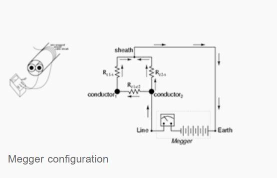
Image: megger configuration for Insulation testing between one conductor and outer sheath
Source: https://electrical-engineering-portal.com/measurement-of-insulation-resistance-1
2nd scenario: testing between conductor 2 and outer cable sheath only.
For this scenario, you have to use the Guard Terminal. The guard terminal removes any connected part from the circuit so that you can measure exclusive resistance between two points. In case you do not use the guard terminal, some leakage current will pass through conductor 2 to conductor 1 and then to conductor 1 to the outer sheath. This will give you faulty readings.
First, connect the Guard terminal to conductor 1.
Secondly, connect the line terminal with the conductor 2.
Thirdly, connect the earth terminal to the wire around the cable sheath.
Now start the megger.
Finally, take the readings.
Now, there is no voltage between the two conductors, no current, and insulation resistance is infinite. The current will only pass through the second conductor’s insulation to the wire around the cable sheath through the cable sheath. Thus, the megger will show resistance exclusively between the second conductor and the cable sheath. It will not show any current leaking through the first conductor’s insulation.

Image: megger with connection in guard terminal
Source: https://electrical-engineering-portal.com/measurement-of-insulation-resistance-1
Insulation Resistance Test Procedure– Testing of insulation resistance of single wire cable
First, connect the guard terminal to the top of the insulator.
Secondly, connect the conductor to the line terminal.
Thirdly, ground the Earth Pin.
Now, start the megger.
The current starts flowing. Note the resistance. It will show readings between 35 to 100 Mega Ohm.
Maintain the contact for at least 30 to 60 seconds.
The acceptable Insulation Resistance value for electric cable is 1 Mega Ohm for 1000V.
Insulation Resistance Test Procedure–Results
If you notice the values of insulation resistance between 35 to 100 Mega Ohms, it is a good insulator.
If you want to test the values of insulation resistance over time, take readings regularly. Plot these readings on a graph. If you notice a steady decrease in insulation resistance, it indicates the gradual weakening of cables and wires. This type of periodic readings is a better tool for insulation resistance measurement rather than spot testing.
Conclusion:
A minor fault in any single wire can lead to considerable losses in the property as well as human lives. So, you must perform preventive maintenance. Further, if you want help with high-quality cable assemblies and wiring harnesses, contact us. We are renowned cable manufacturers dealing in a wide array of them. Give us a call, and we will respond to you in no time.
Get Your Free Sample!
Explore our custom services now. Email us at sales@wiringo.com for more details.