You expect nothing less than Allstar performance from your race car wiring. That’s why you need the best automotive wiring adjustments. It’s a challenge the find the right setting. However, it enhances the safety and reliability of your ride. Additionally, it makes it easier to maintain.
This guide focuses on race car wiring. You’ll discover the right and wrong ways to hot rod wiring and discover the dos and don’ts of the process!
What Are the Main Race Car Wiring Principles?
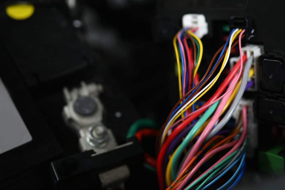
Caption: Multicolored wires in the engine control unit
A reliable rod wiring harness applies several principles. If you stick to them, you ensure everything works right. Check out some main cautions and things to consider during the process!
Dropping Voltage
Have you heard about a “dead short?” It should be the lowest resistance that still enables painless performance. However, race cars are very demanding. Therefore, there’s no room for mistakes in their electrical systems.
If you face even the smallest resistance, it can lead to major problems. You’ll have huge current potential if you mix ignition wire with solenoids. It could exceed 30 Amps. Therefore, the estimation of the voltage drop between cable ends is three volts. That implies you could face many unpredictable situations.
While you can’t avoid some resistance, you want to find the best way to manage it.
Transient Voltage
If you say transient, that indicates a short-term event that occurred because something happened in the electronic system. So, if you deactivate a solenoid, you generate a huge voltage for a microsecond. Although that is a short time, it’s enough to cause problems with other components. Your automotive wiring has many parts.
Therefore, it’s impossible to predict where the transient voltage will go. You can manage it using a quality wiring harness and diodes throughout the coils. Furthermore, install a diode in every relay or solenoid in the vehicle.
Wiring
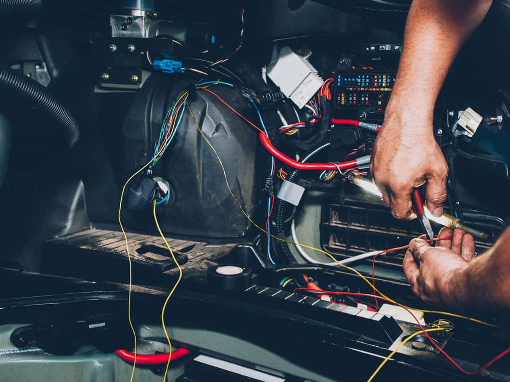
Caption: Bundle of wires for automotive wiring
The first rule is that a control device shouldn’t share a connection with the power wire. It’s smart to use separate wires for power connections. You won’t solve a problem by adding another ground. Furthermore, that can cause more issues than resolve them. The approach should be to create two separate buses. So, the first one is “dirty” and handles large currents.
The other is a clean bus, which aims to reduce the risk of voltage dropping. It’s imperative to have a quality wiring harness. You might invest a bit more but minimize the risk of damaging the vehicle’s components.
Chassis Ground
The experts recommend minimizing reliance on chassis grounds. It’s better not to connect grounding parts to the chassis harness.
The alternative is to find the grounding in the appropriate bus. Furthermore, don’t connect the chassis to the clean bus. You should only attach it to the negative battery terminal.
Five Ways to Wire a Race Car
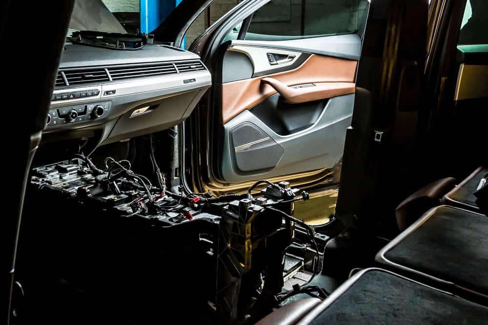
Caption: Serviceman working with auto cables
There are multiple ways to wire a racecar, so picking the right one is vital.
Extremely Wrong Way
Can you believe that most cars have this wiring? It involves using both batteries’ sides – positive and negative – for various components. Therefore, you connect noisier devices, fans, pumps, and electric motors to a single wire on both sides.
Furthermore, you apply the same approach to digital electronics. The problem is that voltage drops are probable. Additionally, what if you deactivate the current on a fan? It can lead to a voltage spike in other components through common wires. So, this could easily damage your car. Therefore, you want to steer clear of this wiring diagram.
Wrong Way
You can add two wires to the positive battery ground. That way, digital electronics have a separate wire from solenoids and other electrical connections.
On the other hand, these devices and digital electronics share the same negative wire. That could lead to potential problems, such as voltage drops and spikes.
Another Wrong Way
What if you use an opposite approach to the previous one? So, you add two wires to the negative battery but use a common cable for the positive charge.
Once again, the problem is sharing the same wire. Therefore, you could face drops in voltage and electrical noise. Furthermore, a voltage spike might occur if you deactivate the current for a specific component.
Good Way
Caption: A futuristic concept of a race car
Although you’ll use four cables, this will still be a simple wiring diagram. So, the idea is the following:
Connect two wires to the positive and the negative side.
Attach your fans, pumps, noisy devices, and other components. Additionally, connect the cables to the digital electronics.
The electronics receive current from the wires differently than those used for solenoids and motors. That implies there’s no shared path, meaning there’s no voltage drop risk. A slight drop might occur if a large-load component draws power from the battery. However, that’s insignificant compared to the methods described above.
The Best Way
The best method is copying the previous diagram, which has a vital edition. You add a diode across the power wires to absorb the transient voltage.
If you deactivate the current on a solenoid or another component, it generates a huge transient voltage. It only lasts for a microsecond, but it’s enough to damage other components. Therefore, you add the diode to prevent sensitive components.
Do’s and Don’ts for Race Car Wiring
Caption: A mechanic checking car wiring
Would you like to know how professionals handle that bundle of wires on a race car? Here are some tips on how to handle a wiring harness on your vehicle:
Use zip ties. These will secure your wiring harness. Vibration is a frequent problem, so use zip ties as a solution. Additionally, your wiring harness will look better.
Don’t make wires longer than necessary. Unless you bought custom cables, their length is longer than you need. Therefore, you should shorten them. If you leave them too long, you make a mess. Furthermore, a longer cable loses voltage with every inch.
Solder your wiring. You might think about crimping the connections. However, it’s better to solder them. It ensures a better touch of the connector and the cable. Furthermore, it ensures vibrations won’t loosen the connection.
Don’t forget to set a master disconnect switch. It ensures a simple way to remove all electricity from the battery. It’s an emergency option but can protect your vehicle.
Apply grommets to protect the wiring harness. Do you need to pass a cable through a firewall opening? If yes, a grommet will ensure optimal protection.
Check if everything else works. That includes inspecting your steering column wiring harness and other parts. That ensures the vehicle will work well on the road.
Conclusion
If you want maximum performance from your car, the wiring should be optimal. Ensuring your race car wiring harness is ideal takes a little time and effort. If you need some tips regarding your cable assemblies, don’t hesitate to contact us! Our wiring harnesses are the best choice for your car to achieve maximum performance.
The steering column wiring harness is imperative to your vehicle’s work. Its primary function is to connect the wheel to the steering mechanism. Additionally, it secures mounting for multiple components and manages energy dissipation if a collision occurs.
This guide explains everything about the steering column. You’ll learn to recognize a failing column and install a new one. Furthermore, we provide detailed assembly instructions and a wiring guide!
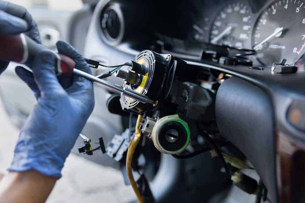
What Are the Signs of a Failing or Bad Steering Column?
Caption: Car steering wheel repair
If the steering column starts failing, there are ways to recognize it. So, here are the signs of a bad component.
You Can’t Lock the Steering Tilt Feature
The tilt feature allows setting the wheel’s location and angle. Therefore, you have better comfort and easier operation. You activate the function so the wheel moves around until it locks into position. So, that means it’s at an optimal angle and height for the driver. If you don’t find the wheel is locking, that indicates a problem. Therefore, you should check the column and other parts inside it.
You Hear Noise When Turning
Caption: Women driving a car
Does it seem like you hear the steering column when turning? It could be clunking, clicking, grinding, or squeaking. Furthermore, you might only hear it during more difficult steering endeavors. The more often you hear it, the sooner you should check it out. Otherwise, it could become a serious problem and even cause accidents.
The Wheel Won’t Return to the Original Position
You make a turn, and the wheel returns to the default position. So, that’s the way it works with vehicles. It’s a safety function of power steering. If it doesn’t work, that means something is wrong. A broken gear in the steering column could be the cause. Therefore, you should call a professional and handle the fix now.
Rough Operation of the Steering Wheel
Caption: Man driving a car
If you drive your car daily, you know when something is wrong. Did you notice something weird when operating the wheel? It could be that it’s difficult to turn. Perhaps it pops while turning, which indicates a steering column issue. Debris and dirt often cause gear blockages. Therefore, this might disrupt the wheel’s operation. It might not be a demanding fix but handle it now.
How Much Does It Cost to Replace a Steering Column?
Caption: The components of the car in a repair shop
The price of replacing a steering column varies. Therefore, you should consider two things – the components and the mechanics. If you go with the latter, make sure to get several quotes. That way, you can find a mechanic who offers the best balance of affordable price and quality.
Your car model and make will affect the total labor costs. The experts recommend this fix cost anywhere from $500 to $1,500. The replacement will be cheaper if your car has a simple steering column design.
On the other hand, other components might make work harder. Cruise control, radio controls, and complex wiring can be in the way. They will require additional work so the price will be higher. For example, you can change the steering column for $675 on an older Dodge Caravan. The replacement of the Honda Accord costs $800. On the other hand, you’ll need $850 for Honda Civic. If you need a steering column for Ford F-150, it will cost you over $1,000.
You can save some cash if you handle the fix. The estimated savings can be huge. That’s because you’ll only need to spend money on the equipment.
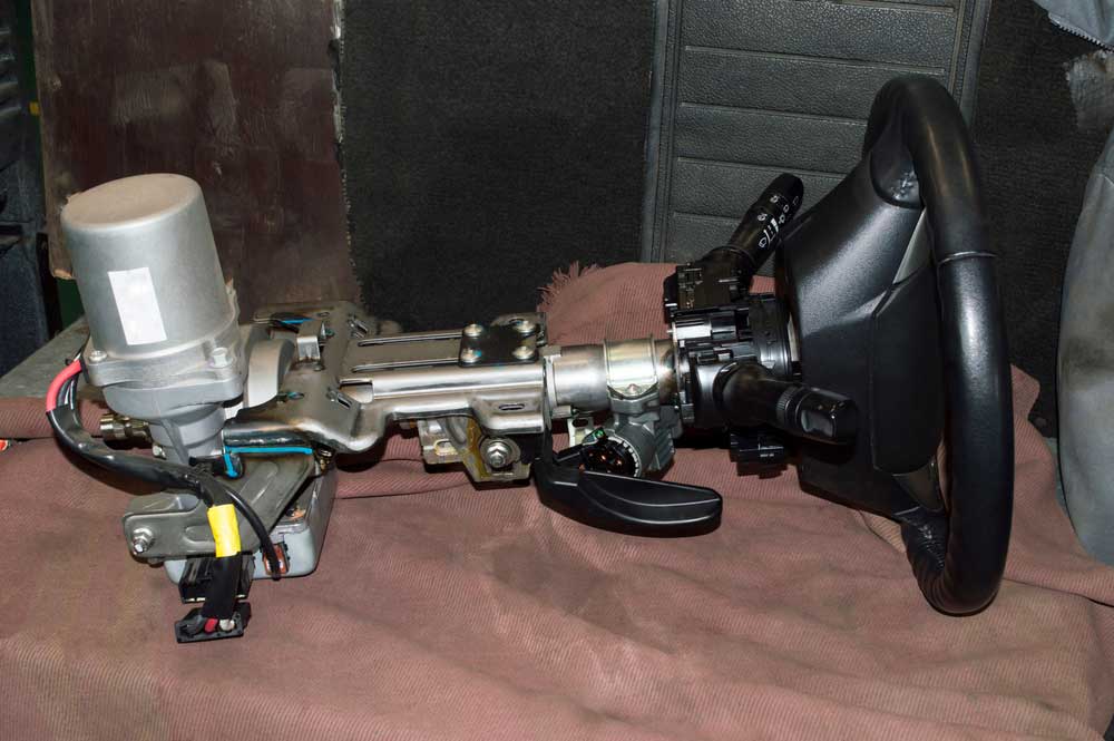
A Guide to Installing a Steering Column
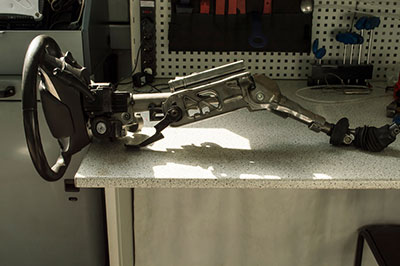
Caption: Car steering column isolated on a white background
Does your aftermarket column need an installation? The setup isn’t hard, but it requires time and effort. Therefore, set aside an afternoon. Now, here are the steps to follow:
Remove the negative battery cable.
Be patient because you need to deactivate the airbag. So, give it about 20-30 minutes before continuing.
Disconnect the plastic connector trim and hush panels.
So, you’ll find the former under the steering column. On the other hand, look below the dash and find hush panels.
Take out the knee bolster.
You’ll find clips holding it in position below the column. So, remove them, and do the same with any screws. Additionally, take out the steel backing you now uncovered. You’ll need to remove bolts to do this.
Furthermore, point the front wheels ahead. If necessary, use the seatbelt to hold the steering wheel in place.
Take out the pinch bolt.
You’ll find it on the steering coupler as it connects the gear to the column. Make sure that the wheel remains in position after disconnecting. Otherwise, you could risk ruining pricey components. You’ll probably need a new automotive wiring harness, too.
Disconnect column wires.
If you notice any on the steering column, remove them. Are there nuts that connect the dash to the column? You can remove these, too. Finally, you can take out the steering column from the car.
Insert the new column.
You want to tighten it to the dash and position it inside the coupler. Additionally, point the column’s wheel ahead.
Tighten the pinch bolt and reconnect the cables.
Once you finish, position the knee bolster and steel backing into place. Insert the hush panels and any trim.
Return the battery.
This is the final step, so get ready for testing. Make sure everything works before going on the road.
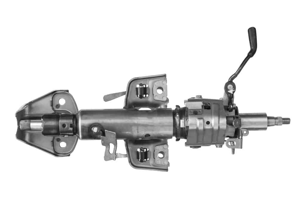
How to Assemble a Steering Column?
Caption: A 3D illustration of the steering column
You should assemble a steering column before installing it in the vehicle.
Turn the signal lever.
You should place it in the column’s left-side hole.
Next, connect it to the white mechanism with the offered screw. On the other hand, you shouldn’t overtighten it.
Tilt lever and flasher knob.
Find a small hole on the column’s right side. Thread the flasher knob onto it.
Next, find the left-side hole and mount a tilt lever.
Shifter arm.
Find the shift arm spring and apply grease to it.
Now, please insert it into the spring hole. However, please note a screwdriver might be necessary. Next, move the column’s collar by twisting it.
Furthermore, twist it until the gear indicator comes into the Neutral position. While you push the shift arm inside, you’ll notice the spring goes deeper into the hole.
Finally, align the lever’s hole with the column’s one.
Next, insert the lever pin to connect the holes. Use a hammer, if necessary, to push the pin until the hole is flush.
Steering wheel.
The first thing to check is whether there is a compression spring below the canceling cam.
Now, you want to place the horn connection. So, you want it at the angle between 10 and 11 o’clock. You’ll find a metal spacer below the steering wheel and above the black horn-canceling cam.
Place the adapter or the steering wheel onto the shaft of the splined column. Thread it on the column shaft screw nut.
Finally, tighten it until you find an optimal setting.
Will replace the steer column stop signals from working? If you don’t handle it properly, yes. So, make sure to follow the instructions to ensure everything works right.
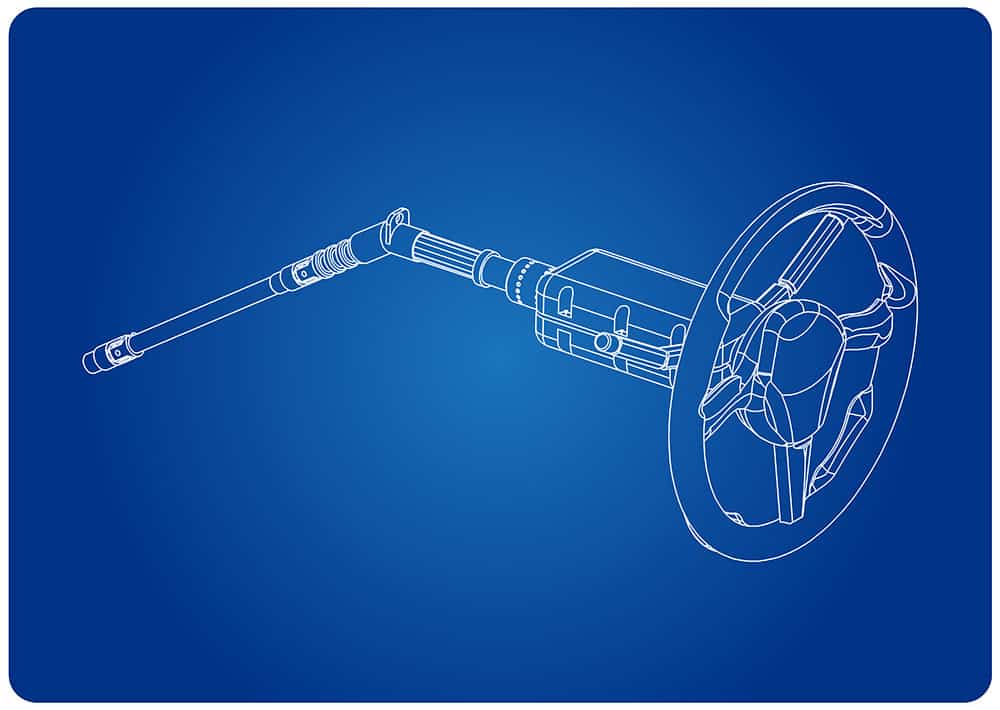
A Wiring Guide for the Steering Columns
Caption: Steering column and wheel on a loader
There’s no need to be afraid of wiring if you know what you are doing. Your car might require a custom cable assembly, so get one if necessary. Before we do that, here are the two major components to consider:
Standard Turn Signal Switch. General Motors has used the same switch type for over two decades. The changes between types are minor, so there shouldn’t be major differences.
Connector Plugs. These depend on your application. Therefore, you might need 3 7/8” plugs. On the other hand, you could use bigger or smaller. The plug’s bottom has letters. So, each letter corresponds to a particular wire. Therefore, this is the guide to use when wiring steering columns.
Now, let’s check the different wires:
White. You connect it to terminal P on the harness plug. It serves as the brake light feed. Therefore, the cornering lights and turn signals can work even if you are braking.
Green. So, find the N letter on the plug and connect green wires to it. Thanks to that, the right rear turn signal and the brake will work.
Yellow. This one gives power to the left rear turn signal and brake lights. Therefore, you connect it to the M terminal.
Purple. It goes to terminal L on the plug. Furthermore, it’s important to send power to the turn signal switch. If you don’t have a fuse panel, hook it to a switched lead.
Brown. So, this wire goes into the K terminal. That will ensure the four-way flasher works.
Dark blue. You have two blue wires, so pay attention to their tones. Therefore, connect the dark blue one to terminal J. You send power to the right front turn signal and auto indicator light.
Light blue. This one gives power to the left front turn signal and indicators. You connect it to the H terminal, so don’t mix it with the dark blue wire.
Black. Find terminal G and connect the black wire.
That will ground the horn, but it doesn’t send power. Make sure not to feed the power to this wire.
Otherwise, you could face issues that require spare parts.
Conclusion
We hope you now understand the steering column wiring harness. If you have a quick question or need cable assembly assistance, please get in touch with us!
And the classification and function of SATA cable, the price of SATA cable, and how to buy it.
This article will be the best guide for learning about SATA cables.
Let’s start.
CHAPTER 1 – What is a SATA Cable?
SATA cables
SATA or Serial ATA or Serial Advanced Technology Attachment was introduced as an IDE standard for connecting hard drives and other optical drives to a motherboard in 2001.
Any cable that is compatible with the IDE standard is called a SATA cable.
We know SATA cables replaced the older PATA cables used in computers and transmit data much faster than the PATA cables.
You must have seen a SATA cable with the seven-pin connector that connects your hard drive to the motherboard.
The same cable is also used to connect other SSD devices and carry power.
The cables are generally thin and flat.
The connectors also follow the same design pattern. You may also hook up external hard drives using SATA cables with the SATA input of your CPU.
PATA Cables
Besides being faster than PATA cables, SATA cables permit external and internal hot-swapping devices.
You don’t need to switch off the devices before removing them from SATA connections.
On the other hand, your whole computer had to be shut down if you wanted to remove a hard drive using PATA cables.
And SATA cables are not compatible with some older technology and devices.
In that case, you can purchase separate adapters to solve the problem.
For example, buying a SATA USB adapter can run your external hard drive through a USB.
These adapters can come in handy when you are transferring data from older drives to newer ones or want to wipe them completely.es
CHAPTER 2 – The Types of SATA Cables
You can probably find different SATA cables for data transmission and powering your drives and SSDs.
As a result, in this chapter, we will examine the most common types of SATA cables.
2.1 SATA Power Cable
SATA cables are generally used for connecting hard drives and the sort.
However, if you open your CPU, you will see many SATA cables that supply and distribute power to many internal devices.
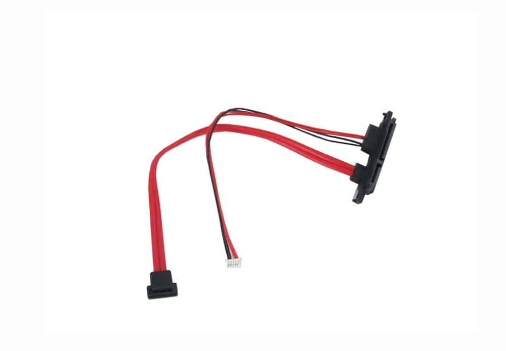
SATA power cables have power connectors at one end and utilize the friction caused by connector bodies to stay adhered.
Generally, the SATA cables are flat and power the storage devices connecting them to the CPU power supply.
And it has replaced the four-pin Molex connectors, which used to be used in older computers.
Cables differ according to the driver type and specifications of size.
Sometimes you may purchase a complete 22-pin SATA wire that combines the power and data connector, but they are not so flexible.
SATA power cable
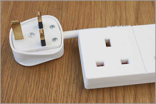
2.2 Monitor Power Cable
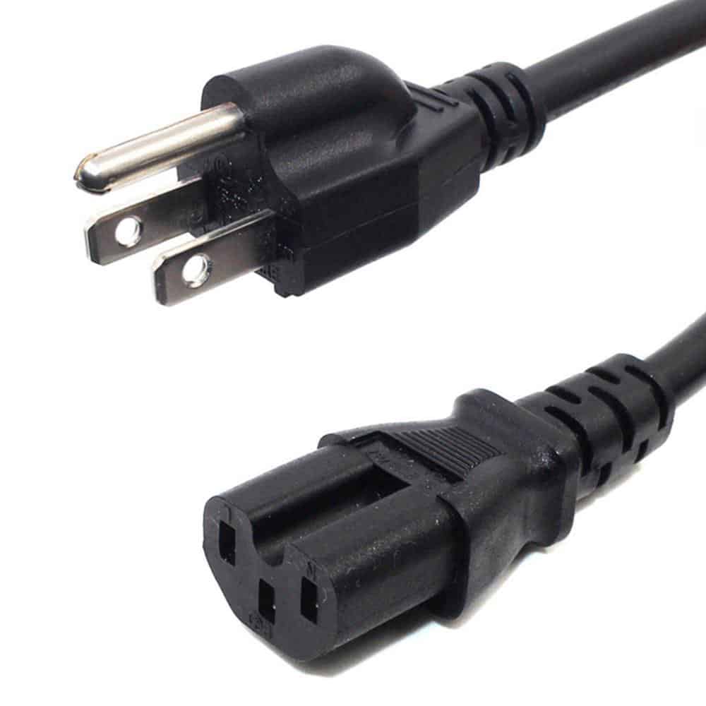
Monitor power cables are sturdy and thick and provide a power supply to your monitor.
It has a three-prong connector at one end, while the other has a standard AC power plug.
It would help if you connected the plug end to the power outlet while the other connected to the monitor.
It is always better to use good quality monitor power cables as they carry a significant electric current.
2.3 Hard Drive Power Cable
The primary job of a SATA cable is to connect hard drives to the motherboard.
However, the same cable is also used to power your hard drives.
Your hard drive has multiple inlet ports, among which you will find a port to connect the SATA power cable.
One end of the power connector will go into your hard disk while the other is connected to the SMPS.
You will generally find the wires supplied with your SMPS or hard drive, or you can also purchase them separately.
SATA hard drive power cables have replaced the older four-pin Molex connectors used earlier. The power cables are generally flat and thin to maximize airflow inside the CPU and lessen cable entangling.
2.4 PS4 Power Cable
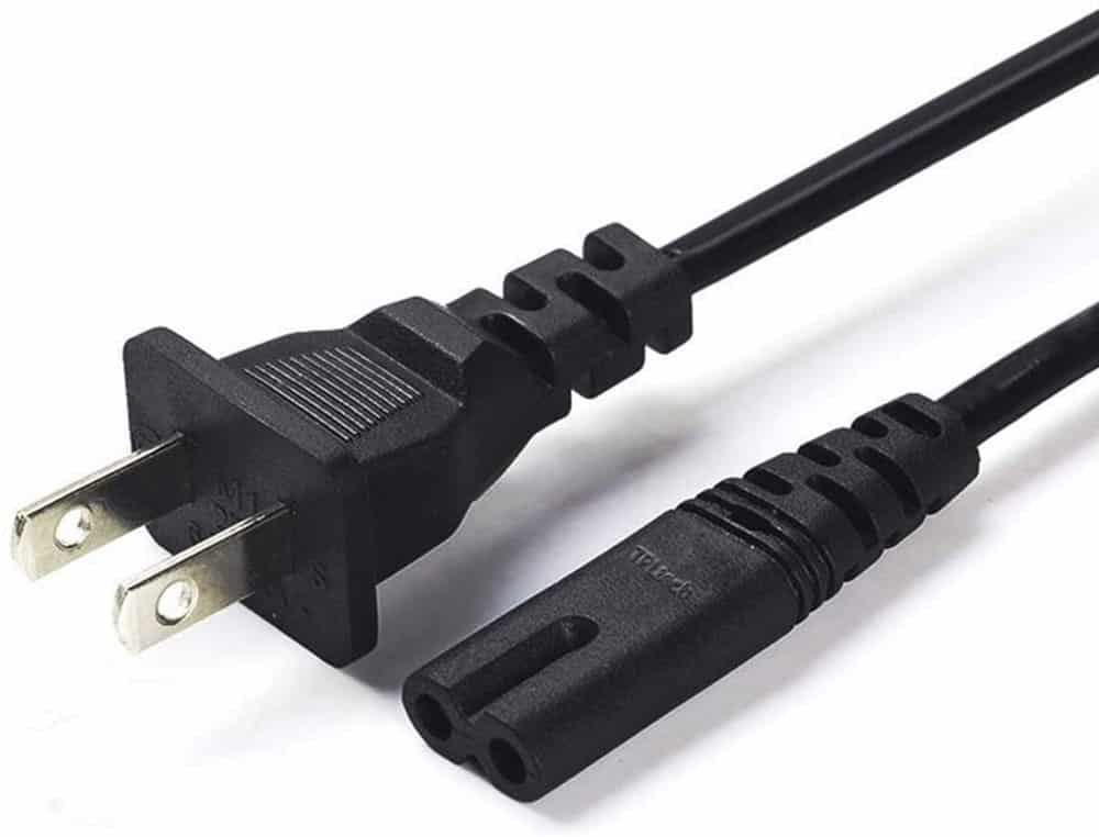
Sony PlayStation or PS4 uses a power cable similar to the audio cassette players of the old days.
The power cables come with a double-end female connector and a standard AC plug.
It would be best to connect the female end to the adapter provided with your PS4 while the plug on the other end goes into the power outlet.
Different wires are available for your PS4, but it is wise for SATA cables to go for original or high-quality cables to protect your device.
PS4 power cable
2.5 SSD Power Cable
SSD or solid-state drive storage devices have many advantages over mechanical hard drives.
They perform faster and don’t suffer from performance issues like older drives.
You can purchase external SSD drives for affordable prices, which brings the question of the power cables.
You must install the power cable correctly if you want to use an SSD as an internal device in your CPU.
The SSD power cables are SATA cables with power connectors.
They will be sticking out from the SMPS of the CPU, and you need to connect it to the SSD matching the connector.
The SSD power cable provides the power supply to your SSD drive.
2.6 USB Power Cable
You must have great use for the USB ports on your computer, but did you know they also need power?
Of course, you will not need a separate power cable for them- the 20 or 24-pin connector cable provides the necessary electricity.
A single cable will come out; this wire is divided into two connectors at the other end, which you must connect to the motherboard.
2.7 Micro USB Power Cable
Micro USB is the mini version of USB ideal for connecting different devices like smartphones, cameras, and tablets to your computer.
The Micro USB power cable has a USB connector at one end and the micro USB connector or pinheads on the other.
The same cable can transmit data or charge your devices per your requirement.
Generally, all micro USB power cables carry a standard of 5V of the power supply.
Be sure to purchase a matching connector with your device; otherwise, your micro USB cable may be useless!
2.8 TV Power Cable
Older TV sets had power supply cables built into the body, but modern devices have separate cables.
The TV power cables resemble the monitor power cables with a standard AC plug at one end and a three-pronged or two-pronged female connector at the other.
The power connector and type may vary according to the brands and models.
Inspect the input port of your TV power supply and then buy a parallel cable for hassle-free functioning.
Monitor Power Cable
You may be able to find SATA cables with different types of connectors in use.
We have provided an essential guide on the major categories, and next, we will discuss a few more SATA cables.
CHAPTER 3 – SATA Cables
Here is a few more SATA cable you can find in use. Some are quite common, and you may already know about them.
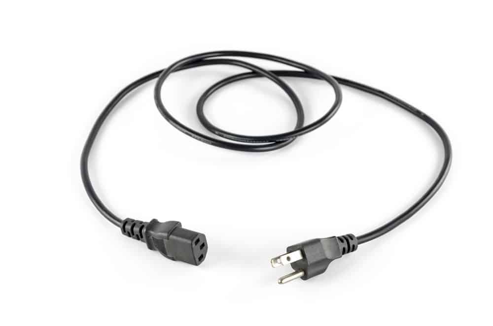
Computer Power Cable
Your computer or CPU will need a power source to function.
The computer power cable is the main wire that supplies electricity to your computer.
The cause is connected to an AC power outlet through the power plug, while the output is connected via the female connector to the SMPS of your CPU.
Cables are made heavy-duty to transmit the required wattage for your computer.
Some computer power cables are compatible with scanners, printers, and monitors.
The wires have a conductor made of metal and an outer layer of protective coating.
The CPU Power Cable
CPU Power Cable and computer power cable are the same things.
The CPU power cables also use a female connector that goes into the male outlet of your computer’s SMPS.
Wires are of good quality and have thick insulation to transfer the current to your computer.
CPU Power Cable
Power Supply Cable
A power supply cable is used for various devices and provides electricity to function.
You can use power supply cables for computers, CPUs, scanners, monitors, printers, and more.
The power cable is compatible with any three-pin power connector equipment.
There is a three-pronged grounded plug at one end, which you must connect to a power outlet.
The other end comes with a three-pin female connector connected to your device.
The power supply cable has a conductor generally made of aluminum or copper.
The outer layer comprises a protective coating covering the entire length.
The wires are also heavy-duty, but you shouldn’t expose them to moisture or physical damage.
Check the connector of your device or read the user manual to determine which type of power supply cable connector you need.
We have given you an excellent course on SATA cables and different power supply cables.
Now the time has come to take things further in the next chapter.
CHAPTER 4 – SATA Cable—Extending Knowledge
The time has come to embark on the final quest for everything related to SATA and power supply cables.
Therefore, this chapter presents a few more things you ought to know!
4.1 Xbox One Power Cable
Xbox One has a power adapter that transforms AC to DC and sends it to your device.
Then you will see a 1.1 meters long DC power cord that comes from the adapter and connects to your Xbox One.
Another detachable AC power cord is around 1.2 meters long and connects to the power source.
The other end of this cable is connected to the 100 – 240 V power adapter.
So you can separately purchase the AC power cable though Microsoft recommends using only genuine replacements.
Most noteworthy, the connector plug that goes into your wall’s electric outlet can differ according to the electrical standards of different countries.
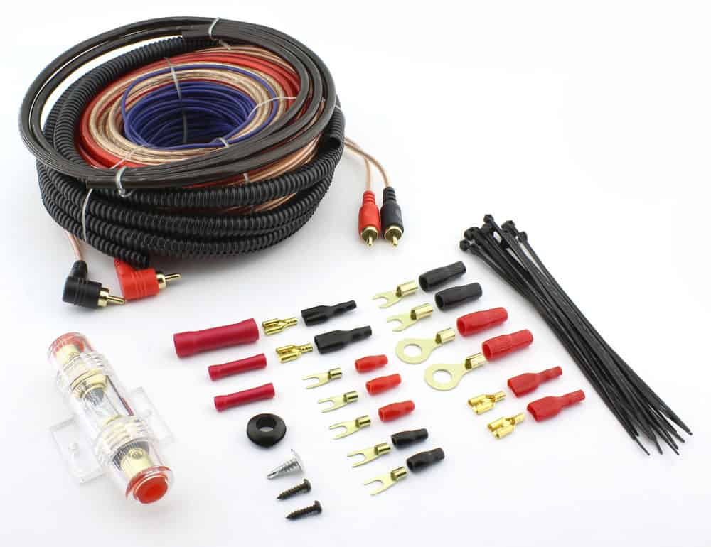
4.2 In-Wall Power Cord and Cable Kit
If you want to do a professional job setting up your TV or audio systems, an in-wall power cord, and cable kit can be handy.
The kit has power cables, sealing tubes, power cords, fish duct tapes, gaskets, and everything to complete your job.
The idea is to set up a cable system through the tube where the wires don’t make a mess.
Cells fit into your walls effortlessly, and you can run the power cables through the tubing from the power outlet to your device.
Furthermore, you can run coaxial cables, audio-video cables anything of the sort through the tubes to hide them from people’s sight. And the result is a neat, clean wall with a perfect electrical system.
4.3 AC Power Cable
AC power cables are used for transmitting AC to compatible devices.
Remember the discussion we had about Computer and CPU power cords?
It is the same cable for devices like computers, monitors, printers, scanners, and any equipment that uses a three-pin connector plug.
Cables come with a 3-point female connector that connects to your device.
AC Power Cable
4.4 Xbox 360 Power Cable
Xbox 360 has a power adapter similar to the Xbox One.
And the adapter connects with a DC power cable that directly plugs into your Xbox 360.
You will also find another AC power cable that goes into the power outlet in your wall, supplying electricity to the adapter.
4.5 Porter Cable Power Tool
Porter is a leading American power tool manufacturer selling different types of equipment to complete your electrical tasks.
Tools are heavy-duty and feature high-quality motors and parts.
You can get small drillers, circular saws, reciprocating saws, flashlights, compressors- anything and everything you need to install your cables and wires.
The instruments run on lithium-ion batteries, which retain a charge for a long time.
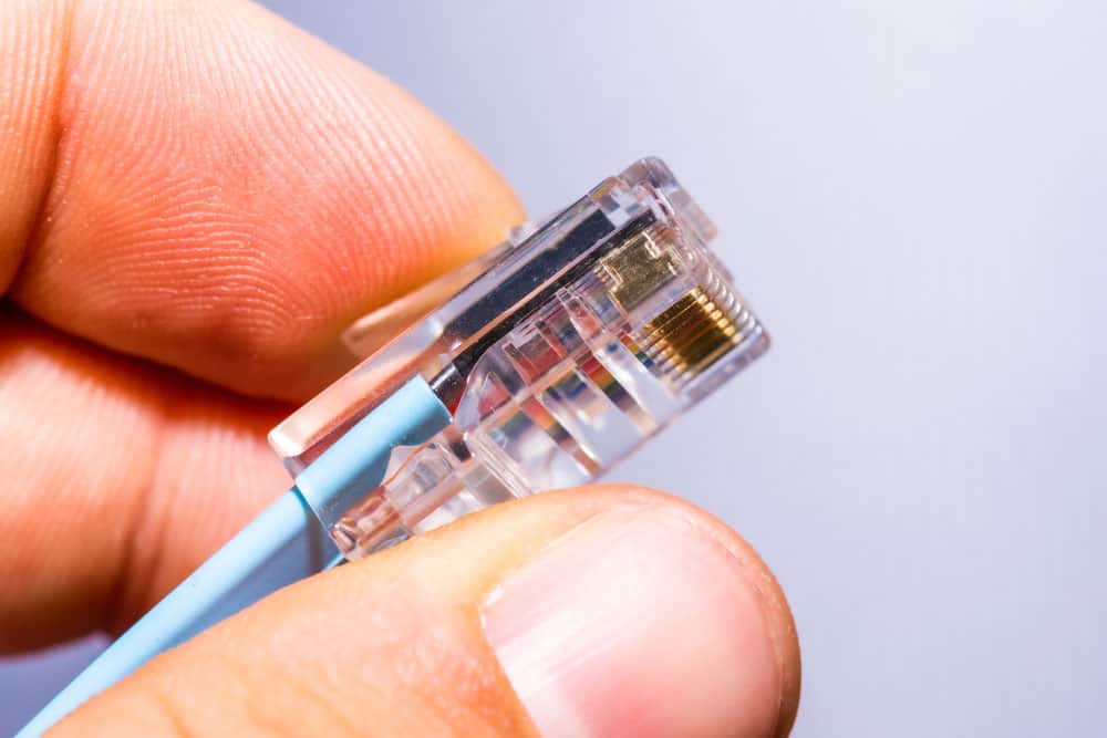
4.6 Power over Ethernet Cable
Power over Ethernet or PoE cables is used to transmit data and electricity over a network to devices such as computing systems, VoIP phones, and security cameras.
The same power cable carries data and electricity to any device connected to the Ethernet network.
The setup can also be done for wireless networks using a PoE splitter and power cable hooked to a wireless access point.
PoE cable is the same Ethernet cable with twisted pair cabling.
After reading the guide, you must wonder how to purchase SATA cables and related considerations.
We will cover the topic for your convenience in the next chapter.
PoE Cable
CHAPTER 5 – Where to Buy SATA Cable
Let’s start with some tips for buying SATA cables.
5.1. Buying Tips
Don’t use cheap thin wires that might cause data or power loss.
Check the different versions of SATA cables. Some have speeds of 1.5 GB/s, while the new versions support up to 6 GB/s.
As long as you have a good quality wire, there is not much difference between the 3 GB/s and 6 GB/s SATA cable.
Check out the connectors to ensure they are compatible with your device and power outlet.
You can use the same SATA cable for different compatible devices.
Compare the price of different dealers to get a good deal.
So, please get in touch with us today for more information.
Conclusion
Your course on SATA cables has come to an end.
We have discussed the different types of SATA cables for hard drives and SSDs and the power cables for various devices.
Now, you have become an expert on SATA cables and will find no problem handling your cable requirements.
Maybe you can even help your friends with their cable installations and get custom cables of different types, including SATA cables, from us for your home and office needs.
Consequently, contact us for a complete overview of our products and find out what we can do for you!
The SAE cable charges vehicle batteries and power various automotive and motorcycle accessories.
You may be confused, about how to choose the right SAE cable. Before answering this question, you need to learn some necessary knowledge.
That’s why we’ve prepared this guide to tell you everything you need to know about SAE cables.
So let us achieve.
CHAPTER 1: What is SAE?
Definition
SAE, or Society of Automotive Engineers, is an international professional association that develops global standards for engineering industries.
The organization’s standards harmonize the production of different cables and electrical equipment types and offer a foundation for all manufacturers to be on the same page.
SAE standards enable manufacturers to improve the quality of products and meet safety guidelines.
The SAE cable in the scope of our article is used to establish a connection between a battery and other devices.
Specification of SAE Cable
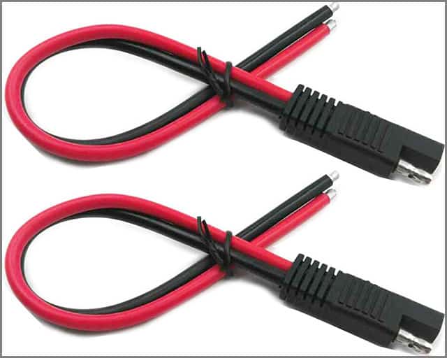
The SAE cable can be called a ‘hermaphrodite’ connector because it features both male and female connectors.
The cables are generally used for automobiles and motorbikes though you can also use them for solar panels and alternative energy applications.
It is one of the components of a PCB soldered to provide extra sturdiness.
The SAE cable comes with two conductors and is commonly utilized to provide a maintenance charge to a car’s battery.
When harnessed with a battery system, the polarity of the terminals is designed to prevent any incidents of the short circuit even if the exposed ends come in contact with the metal vehicle chassis.
For this reason, the exposed terminals of the cable are connected to the negative outlet of the battery.
On the other hand, the positive end of a battery charger is often exposed and hooked up with the concealed SAE connector.
The circuitry of the battery charger also contributes to reducing any possible risks of short circuits.
Lead-acid batteries have higher chances of experiencing short circuits, so you must use a good quality SAE cable to mitigate the risks.
Next, we will discover the implications of SAE connectors and discuss the widely used SAE battery connector.
CHAPTER 2: SAE Connector
The SAE connector is mainly used for automotive applications and solar solutions.
But their versatility means you can also use them for other industries.
One of the common types of SAE connectors is the SAE battery connector.
Let’s find out a bit about it!
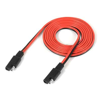
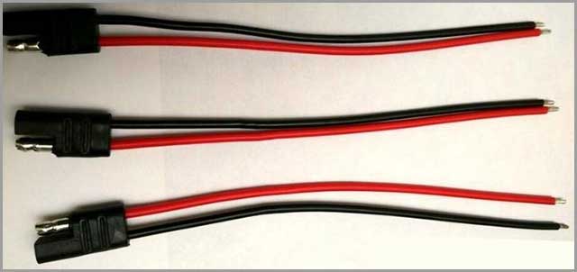
SAE Battery Connector
The SAE battery connector is a simple cable that connects your battery to other devices like chargers.
It has rings or clips at one end to connect to the battery and features a standard SAE connector on the other end.
The cable also has a 15 Amp to 25 Amp fuse to protect the battery.
You can set up the cable and connect a battery tender to charge your vehicle or motorcycle battery.
The SAE battery connectors don’t have the risk of a short circuit even if the unexposed end comes in contact with metal.
For this reason, they are safely suitable for use with different types of automotive parts.
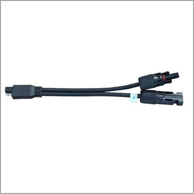
For example, you can hook up a heated vest with an SAE cable with a round end and an SAE connector on the other end.
The SAE cable connects easily with the cable connector to establish a connection.
You can channel the SAE connector from the side of your bike and connect the battery tender or other devices.
The SAE battery connector features two ring terminals which you have to connect to the positive and negative points of the battery.
The terminals are generally color-coded in red and black for your convenience.
You can buy longer SAE connector cables that can measure 25 feet.
These are ideal for use in the garage, where you need power access for the battery charger, which can be located away from the vehicle.
Some manufacturers can use different connectors, but SAE is preferred because they are easy to use, affordable, easily available, and safe.
In the next chapter, we will discuss SAE plugs and then look at the adapter.
CHAPTER 3: SAE Plug
SAE plugs can be used for basic wiring and general-purpose applications in motorcycles and cars.
The SAE plug at the end of the cable enables you to connect different accessories and charger boxes.
Most of the SAE plugs are compatible with motorcycle tank bags.
The SAE plugs are used across different industries and applications such as alternative energy, utility and off-grid solutions, recreational vehicles, vehicle installations, emergencies, and more.
Their versatility makes them suitable for navigation equipment, mobile phones, and laptops.
The SAE plugs are made for low-voltage though you can find many products which handle a higher amount of voltage for use in RVs, trucks, and other heavy-duty applications.
You can find different lengths of SAE plugs for automobiles of all sizes.
After the initial job of setting up the SAE, the plugs are over. You can look forward to a toolless assembly then onwards.
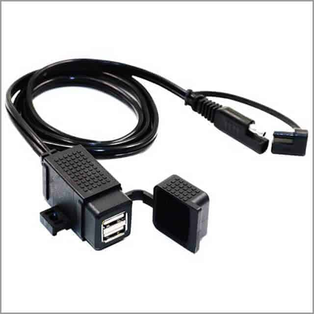
SAE Adapter
You will find different types of SAE adapters that can be used with various applications.
For example, you can have a USB adapter inside your vehicle (we will discuss SAE to USB later) or use a male-to-female adapter to establish a connection.
Another type of SAE adapter is commonly used to connect traditional SAE chargers or jumpstart equipment to newer cables.
These are sometimes used in power sports applications and automobiles and provide an easy way to connect different equipment.
Generally, the adapters are designed to achieve minimal power loss and maximum current flow.
One SAE adapter is common in cars and helps light up your smoke.
The convenient SAE to electrical lighter adapters sit comfortably in the dashboard of your vehicle and are connected to the battery on the other end.
Different accessories and equipment manufacturers also produce custom adapters to accommodate their products.
For example, you can find custom adapters that fit with chargers, solar panels, heated clothing, GPS, and other SAE devices.
Now it turns out to find out more about SAE to USB cable.
The J1127 is the commonly used low-voltage battery cable used in motorbikes and cars to connect the battery to different devices using an SAE plug.
The J1128 is the low-voltage primary cable necessary to charge and jumpstart your vehicle battery.
J2863 is meant explicitly for an automotive trailer tow connector and can withstand high loads of DC.
Usually, you don’t have to confuse yourself by remembering and evaluating all the SAE standards.
The manufacturers of SAE cables duly declare the specifications of their products and the applications so that you can choose easily based on your needs.
We have almost arrived at the end of our article.
Before wrapping things up, we will look at different types of SAE connectors to cables.
CHAPTER 7: SAE Connector to Cable
As we have already discussed, you can use different SAE connectors for the cable.
You need to determine your need and application to choose the right connector.
We will explore the common type of connectors so that you can easily choose.
SAE Connector with Leads
SAE connector with lead is used as automotive cables and is suitable for rearview camera systems.
The cables have a standard SAE plug at one end while the other is exposed to connect them to any wire or connector.
The SAE cables are designed to withstand high heat, oil, solvent, and abrasion levels.
The insulation material gives the cable a low-temperature resistance and high scrape strength.
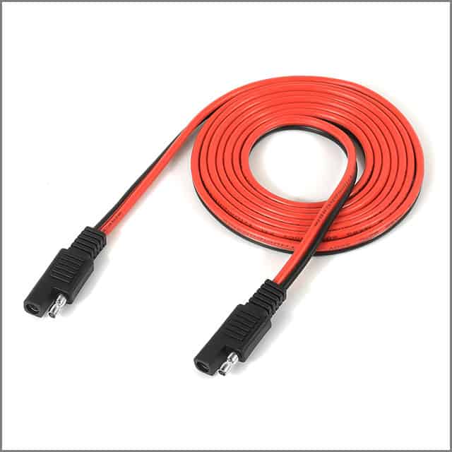
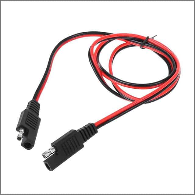
SAE to SAE Connector
As the name implies, the SAE to SAE connector comes with SAE plugs at both ends.
The cables are also suitable for military, industrial, and agricultural use and work with older SAE models without a problem.
The SAE cables are also made to be solvent, heat, and weather-resistant.
You can use them for any application that demands DC power transfer.
Generally, the cables are smaller over a mold, allowing you to fit them in tight spaces.
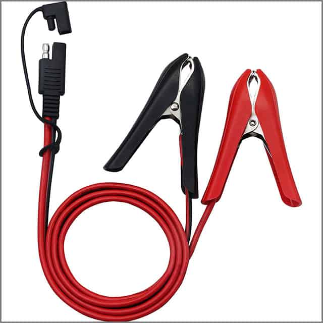
SAE Connector with Battery Clamp
You can take the help of an SAE connector with a battery clamp to supply power to your devices from the battery directly.
It features a conventional SAE connector on one end and two clips or clamps on the other to connect to the battery.
The clamps are color-coded in red and black to know which goes to the positive and which connects to the negative.
Conclusion
SAE cables have many applications in the automotive, agriculture, military, and renewable energy industries.
After reading this post, they come in different specifications, which you must be aware of.
Knowing the specifications is necessary for choosing the right SAE cable and the success of your project.
Why Will You Love Us?
Specialized products like smartphones and laptops cannot be equipped with traditional rigid circuit boards without compromising their compact design or lighter weight.
An ideal solution is a flexible PCB, a comparatively newer technology used widely in medical, automotive, and consumer electronic products.
You can order SAE cables with custom specifications or international standards by contacting us.
We can manufacture high-quality and safe wiring solutions meeting your design and parameters.
Depending on your project, you can go for customized lengths, insulations, connectors, and more.
Cables are among the most common things in the electronics and communication industry.
But you cannot always depend on general cables for critical and demanding applications.
At times, you will need a cable built from scratch.
Or, you may need help with an application, and the stock cables will not work.
In that case, you need custom cables to match your needs and usage.
But do you know which cable to use?
Do you know that you can get custom cables manufactured as needed? If you want to meet your unique cabling needs, it is essential to go for custom cables.
Here is all about how you can choose the right one.
CHAPTER 1: What is a Custom Cable
If you are looking for the right custom cable, expect a wide range of connectivity and network cables.
However, it is essential to look for ones with high standards and ensure that the cables are of high quality, meeting customer requirements for reliability, performance, and cost-effectiveness.
Here are some advantages you will get by purchasing a custom cable.
Better Performance – Custom projects have custom needs.
You cannot match specific stock specifications with them.
With custom-made cable, you can get optimal performance and the materials and ratings you need to complete your project.
Last Longer – When going in for custom cables, you can expect a better shelf life for the equipment.
It is because the cable is made for that particular application and understands its functioning environment.
It has all the attributes and ratings needed to last in those conditions.
Save You more money – While you may think custom-made cables cost more, it may turn out otherwise over the long run.
Yes, the other benefit to having a custom cable is that you will not have to worry about system failures anymore, as you would otherwise when you go in for short-stock options.
You get to Start from Scratch – Since you get to start from scratch with custom cabling, you can ensure that all the needs are met.
So, you can even alter certain aspects of the existing cable to suit your equipment needs better.
We will now look at the types of customizable cables you can get your hands on.
When choosing the cables, do go for one manufactured by industry standards.
Fiber Patch Cords and Jumpers
You can find simplex and duplex jumpers for all compatible industry applications.
This category includes simplex fiber jumpers, duplex fiber jumpers, pigtail fiber jumpers, and micro-armored fiber jumpers.
The cables provide optimized optical performance with low-loss connections.
You can order a custom cable length to reduce congestion and cable stack.
The cables come with a wide range of connectors, such as SCA, SC, FCA, FC, LCA, and LC, for supporting various applications and have extended re-mating capabilities.
You can specify the cable type and choose between single-mode and multi-mode fiber types.
The simplex and duplex cables have 1.2mm, 1.6 mm, 2.0mm, and 3.0mm.
You can order the cables in custom boot colors and custom labeling, and Brady identification.
Fiber Assemblies
You have different fiber cable assemblies such as single-mode patch cords, multimode patch cords, mode conditioning patch cords, fiber ribbon cables, and fiber multi-count trunk cables.
The single-mode patch cords have high bandwidth and performance and are Bend Insensitive.
The SMF-28e cables do not lose light when the cable is bent or twisted as a part of cable management.
The nanostructure technology sends the light back to the fiber core, preventing any loss of signal or current.
You can bend the wires without any problems and experience full bandwidth.
The multimode patch cords are used for LAN applications as the cost of LED transceivers is low.
You can also use them for telephony applications and other compatible purposes.
The cables utilize the technology to offer a high range of bandwidth, 10 to 20 times of regular multimode patch cords.
The fiber ribbon cables are ideal for plug-and-play applications.
The cables are inspected for performance before they are shipped to increase reliability.
Copper Cable Assemblies
You can choose from a full range of copper connectivity solutions to transmit electrical signals between electromechanical equipment and communication devices.
The copper cables are meant to deliver high performance and come with application-specific connectors for different purposes.
Copper cables are ideal for short-distance applications that use relatively low bandwidth.
They also have a low cost of production and can save receiver and transmitter costs.
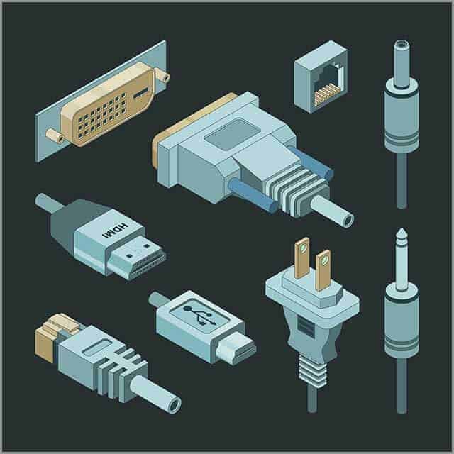
The products in this category include Ethernet cables, office telecom cables, desktop cables, serial cables, audio/video assemblies, and USB and SCSI cables.
The copper cables can connect various computer accessories such as printers, Local Area Networks, and monitors.
They are also suitable for audio-video communications, such as HD TVs and set-top boxes.
The company also manufactures copper cables for offices, data centers, air traffic control towers, and network divisions.
The solution can provide a seamless performance over homerun cabling that can disrupt workflow when you change workstations.
The zone cabling is routed through a series of consolidated points that connect to a cluster of workstations.
The cabling enables the organization to reduce its downtime and costs and can be delivered on a need basis.
RF Assemblies
Braided and corrugated offer high RF performance.
They are suited for critical network applications over a wide range of frequencies.
The cables are produced with the highest standards required for WiMax and 4G LTE technologies and outdoor and indoor DAS installations.
The products under this segment include antenna jumper cables, transmission line feeder cables, mobile cell tower applications, indoor and outdoor DAS installations, and internal radius combiner boxes.
The cables come with Low Passive Intermodulation and quick production lead times.
They offer long-term durability as they are made with a repeatable automated termination process.
Now that you know the different types of customizable cables you can get, we will talk about custom cable assemblies.
CHAPTER 2: Custom Cable Assemblies
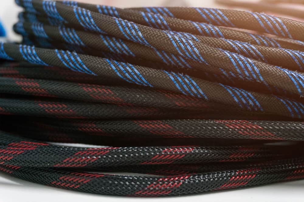
2.1 Custom Cable Sleeving Kit
Cable sleeving makes cable management easier by bunching cables and making them easier to identify.
The sleeving protects the cables from hazards, liquids, chemicals, and abrasions.
You have different types of cable sleeving to buy, including expandable and side entry sleeving.
Expandable Sleeving
Expandable cables come with woven fiber, which gives them some flexibility.
The sleeving is solid in circumference, so you must apply it by passing the cable through it.
The sleeving is ideal for irregularly shaped areas of cables and keeps them secured inside the sleeving.
You can find both reliable and expandable sleeving from Custom Cable.
You need an application that will determine the type you will need.
Side Entry Sleeving
Side entry sleeving is also referred to as wrap-around or split sleeving.
They come with a slit; you must wrap it around the cable instead of feeding it through the sleeving.
The installation process is more natural than expandable sleeving, and you can conveniently wrap the cable isolating the connectors without unplugging any cable.
You can also easily remove any cable by slipping through the slit.
2.2. How to Connect Custom Cables?
If you have different types of connectors, you need different cables to match the applications.
For example, the fiber ribbon connector comes with MTP/MPO connector, whereas the ribbon patch cord features MTP/APO connectors.
The ribbon fan-out cables have different connectors like FC, LC, MU, SC, and ST.
You can choose a cable with a specific connector depending on your purpose.
In the next chapter, we will explore the Custom Cable adapters.
CHAPTER 3: Custom Cable Adapters
You need different types of adapters and connectors for their cables.
For example, you can use coupler-style adapters to establish a connection between the same type of connectors.
The adapters can also help you secure an existing cable with a new piece of hardware or a new cable to an existing piece of equipment.
You can find different such as FAS9A-E2E2-1 PM-FF-CUP, FAS9A-FCFC-1PM-FF-CUP, FAS9F-MJMJ-2PM-FF-CUP, FAS9U-FCST-1CC-FF-ADP, FAS9U-FCSC-1CC-FF-ADP and more.
CHAPTER 4: Custom Cable Services
Wondering how custom cable services work?
We will take a look at how Our PCB does it.
Assembly Division
Cloom delivers dedicated fiber and copper detail engineering for different business processes.
The processes of the assembly division are used for material conformance, performance specification compliance, and component and assembly design.
The company employs various personnel, such as process engineers, to create quality assurance, increase production efficiency and accommodate engineering changes.
The staff helps us provide their services through tooling requirements, equipment maintenance, and process implementations so that they can serve their customers according to their needs.
Network Services Division
Cloom offers on-premise network infrastructure services to businesses of all sizes on local and national levels.
The company provides services based on time, materials, staff augmentation, unit price, and contract to customers according to their requirements.
The customers are assigned a dedicated account and project management team so that consistent quality and service can be maintained.
The company offers the services through qualified and trained personnel fully equipped to do the job.
The Network Services Division and the Assembly Division collaborate on different projects to enable a single delivery source for the customers.
The projects are controlled on an auto-pilot basis, from design and development to assembly and installation.
The company derives value from its direct supply chain and integrates it with a corporate commitment to serve as an enterprise’s trusted network partner.
Cloom delivers its service through a team of qualified and experienced professionals, including technicians, project managers, Registered Communications Distributions Designers, and others.
The company employs its fleet of fully equipped vehicles that can cater to emergency requirements and deployments of short orders.
Cloom offers services to different industries, such as office space, retail, data centers, hospitals, distribution centers, etc.
The network services of the company include-
Assessment and Design: The service comprises many steps, such as site surveys, design and needs analysis, implementation planning, materials selection, and wireless mapping.
Implementation and Installation: The company offers copper and fiber infrastructure, wireless networks, equipment installation, sound masking, fiber splicing, testing, last mile FTTx and CCTV installations.
Maintenance and Upgrade: This service involves UPS upgrades, WiFi overlays, upgrades, network move, add or change, bit error rate testing, fiber characterization, commissioning/decommissioning, and others.
We have discussed the services of OUR PCB company. Now let us take a look at the solutions of OUR PCB.
CHAPTER 5: Custom Cable Solutions
Cloom delivers connectivity solutions for a wide range of industries.
The solution can be customized based on the need of the industry and specific business.
The different solutions of the company include-
Telecommunication Solutions
The company offers fiber optic and copper connectivity solutions for broadcasting and telecommunications.
The network cables are used for data centers, campuses, enterprises, and residential applications as they enable quick data transfer.
Cable technicians can use custom cables to meet critical network needs.
The cables are also applicable for high-speed internet, which requires the exchange of high amounts of bandwidth.
It cannot be very clear for people new to all the new inputs and outputs, knowing all the new devices and methods.
You may face situations that require you to switch your display technologies.
Your video signals can be adapted in both directions between VGA and HDMI.
Still, it is useful to know about the different limitations and cost differences between each connection.
CHAPTER 1: VGA to HDMI
Before getting into conversion methods, you must understand what VGA and HDMI mean. VGA stands for “Video Graphic Array.”
VGA became the fundamental lowest denominator for every computer graphics system in previous years.
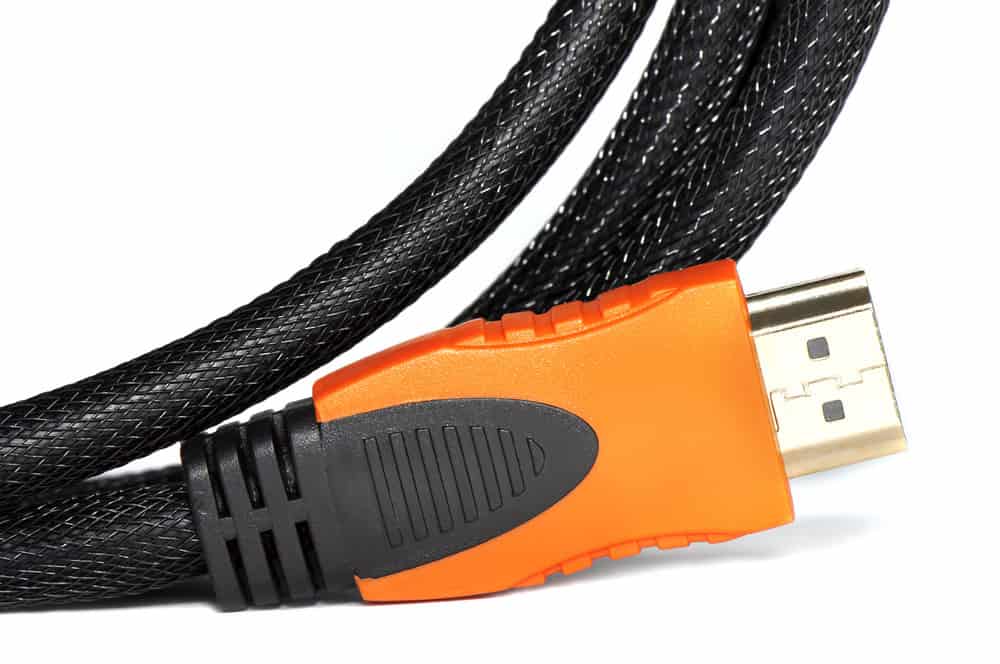
Meanwhile, HDMI stands for “High-Definition Multimedia Interface.”
The now more common interface digitally transmits audio and video signals using an HDMI-compatible source.
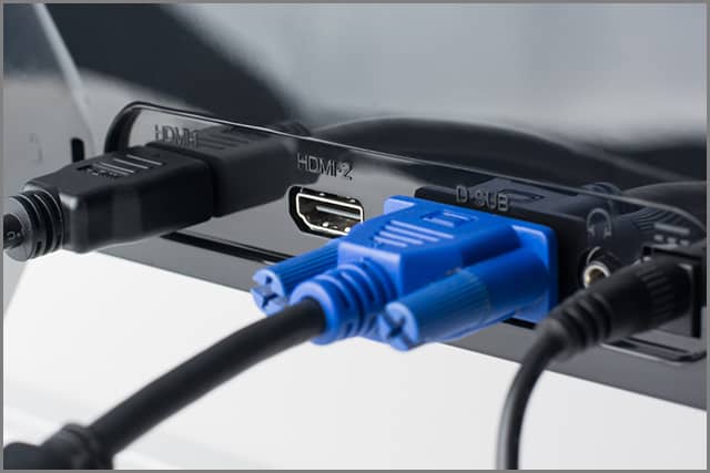
There are two main definitive differences between HDMI and VGA sources.
The first difference is the interface type, with VGA analog and HDMI digital.
The second one is that VGA only provides video transmission, whereas HDMI involves audio and video transmission.
Due to these differences, you will require not only a cable when connecting an HDMI device to a VGA device, but for the conversion to occur properly, you will also need an adapter.
That being said, it’s great to know that these adapters are compact and cheap, most averaging around 20$.
Generally, devices with a VGA interface provide reduced video resolution compared to newer HDMI devices.
PCs that use the VGA interface have to work with lower video resolution due to limitations with the video card.
As for previous displays using the VGA interface, you usually have a problem with screen resolution.
CHAPTER 2: Can VGA to HDMI Carry Sound?
I think it’s safe to say that you now know that VGA interfaces cannot transmit an audio signal.
It is also accurate for situations where VGA is converted to HDMI, even though HDMI does provide audio.
To utilize audio support in such cases, you’ll have to get a separate cable that acts as an audio channel.
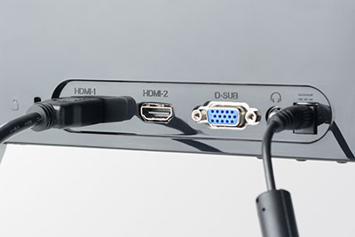
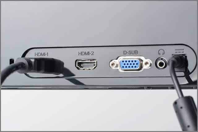
Usually, a PC or TV set comes with the basic 3.5mm audio port.
It resembles a regular headphone jack, and in laptops and computers is the main headphone port.
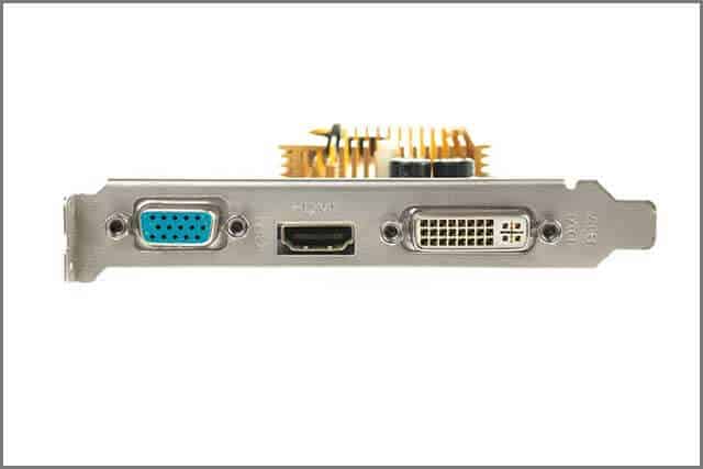
Occasionally, your TV set can also come with an audio port and an HDMI port to connect your computer that uses a non-HDMI interface (such as VGA or DVI).
In these situations, you’re in luck since you’ll only require the 3.5mm audio cable without any other conversion technology.
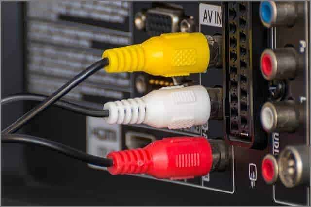
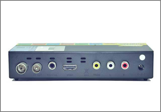
Sometimes there are audio inputs seen in devices known as RCA connectors.
These audio connectors can also be called component audio connectors. However, a regular person would recognize them more easily as the colored ports in a TV: red, yellow, and white.
A video is transmitted using the yellow port, whereas the white and red RCA ports are designated for audio signal transmission.
If your TV monitor needs an RCA for its audio, i.e., only the red and white, you must get an affordable 3.5mm audio port to the RCA device converter.
CHAPTER 3: VGA to HDMI Converter
Many technical things must happen simultaneously to change a VGA signal into HDMI.
These things usually involve connecting these two interfaces.
For this to happen, it is essential to transmit the VGA signal using a converter that will send the VGA’s analog signal and your stereo’s audio to change them into digital transmissions.
These will then be relayed through your HDMI cable to connect with a monitor with an HDMI connector.
The converters register the analog signals delivered to them from the computer or any other device and then convert those signals into digital so that the HDMI monitor can read them.
This process occurs without any obvious breaks or input, so you must connect the devices.
While the conversions between the two different signals are happening between the device and converter, the video images simultaneously fit according to size and format for your display monitor.
Most converter scaling can also accommodate image resolution changes for widescreen monitors.
That said, when choosing one of these products, you need to be aware to ensure that the converter has the necessary input connectors you will need.
Certain VGA to HDMI converters can also come with something that is known as composite video input, basically a round, yellow RCA connector.
Others come with the previously discussed composite three-colored RCA connector.
Either way, both will try to change to the digital HDMI signal.
While these input devices aren’t exactly “VGA,” they are commonly known as VGA to HDMI converters.
Most of the typical VGA to HDMI converters can differ, with the main differences being:
The type of connector that is accepted can be VGA, composite, component, or S-video)
The accepted base resolution
Which aspect ratio or ratios can the converter work with (regular 4:3 or widescreen 16:9)
The provision of any additional switcher that will allow users to work with multiple inputs (that said, having multiple inputs doesn’t technically mean that you can alternate between them)
The provision of any DVI output connector (HDMI and DVI share similar video signal characteristics with the absence of audio within a separate connector package)
The resolution of the output, which can be 480p, 720p, and 1080p
The power sources
The option of having TOSLINK digital audio connectivity
The converter settings can vary between automatic, manual, or even automatic, along with manual overriding.
Section 3.1: VGA Output to HDMI with audio support
Since a converter does not provide audio, you’ll need additional support.
That’s where an audio adapter comes in.
You can find multiple options or packages of converters that come with audio adapters suited for your PC, TV, or laptop.
They’re usually inexpensive and can work well with most older devices.
You must ensure the cables and adapters are compatible with your ports and system requirements00.
Section 3.2: How do I connect VGA output to HDMI?
Now that we know about the different interfaces and their connection and conversion methods, it’s time to start the main task.
Connecting an older VGA interface to any monitor or TV using an HDMI device is simple, but you will have to undertake some purchasing on your part:
Get any VGA output to the HDMI converter box.
Find your VGA cable, which generally comes along with any computer.
Connect the VGA cable to the computer’s VGA output.
Plug the remaining side of your VGA Cable into the VGA input of the converter box.
Connect the HDMI output to your converter box.
Plug the HDMI input port of your HDMI cable into the TV set or computer monitor.
Once you have turned on the computer and your HD Device, you will display the computer video on the HD device.
CHAPTER 4: VGA Output to HDMI Cable
The first component of the conversion system is a converter cable.
It is important to note that for the VGA source to be converted to HDMI and vice versa, your converter will have to be an active device compared to a passive device.
It means that one component will provide passive conversion without any switches between the directions.
Now to understand the VGA output to HDMI cable.
This type of converter will not connect a VGA system to an HDMI one since VGA sources receive analog signals instead of HDMI sources receive digital ones.
Using a cable for transmission will only cause a passive connection since either device won’t read the signals.
That is why you require an actual conversion to connect the systems.
The cable can be used with an appropriate adapter to get the appropriate conversions.
These cables are also very cheap and easy to connect.
Converter boxes are generally ideal since they do the entire activation process.
CHAPTER 5: VGA Output to HDMI Adapter
Another way to connect your old PC device to an HDMI input in a monitor or TV is by using an adapter.
You will require a converter if your PC only comes with a VGA output.
To use the converter, you need a VGA to VGA cable (male connections_ along with an audio cable.
Use either a stereo mini to RCA or an RCA to RCA (both male connections), which depends on the output you get with your sound card.
You’ll also require the HDMI cable to plug the VGA output to the HDMI adapter into your HD device.
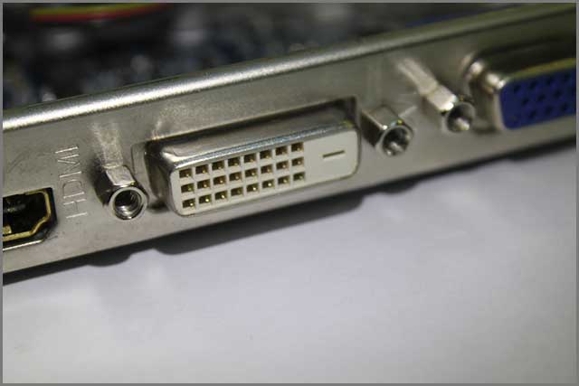
If the computer utilizes a DVI output, you’ll have to get a DVI to HDMI cable, or else you can get a DVI to HDMI adapter along with a regular HDMI cable.
These options are typically more restricted if someone has a notebook computer with no HDMI output since you cannot switch your graphics card.
Even if this were possible, you would still be unable to incorporate the HDMI output into your notebook chassis.
In the end, your only options are to get a converter, as we discussed previously, or get a more modern notebook computer.
CHAPTER 6: HDMI Females to VGA Male
An HDMI output to VGA converter is generally an inexpensive cable.
It can transmit an HDMI signal from a device to a VGA interface on a much older display.
Since VGA is growing scarcer with time, you should only use this connection choice as a last resort.
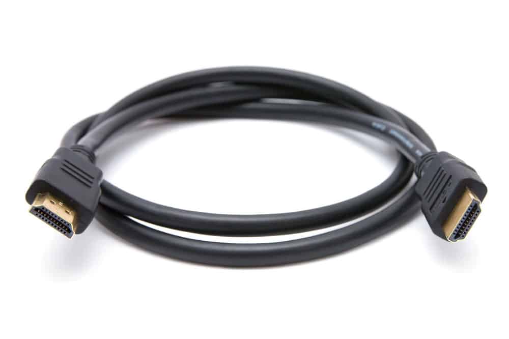
You should know that an HDMI cable can send audio and video signals through one cable.
That said, VGA cables are only able to transmit a video signal.
Suppose you want to have audio and video. In that case, you will have to get yourself a converter with a VGA cable and a separate audio cable or USB device with audio capability.
The process is pretty similar to VGA output to HDMI conversion.
Now, here’s where it gets a bit tricky. You may choose between male HDMI to female VGA converters or vice versa.
That definitely will sound very confusing to anyone new to the technology world.
However, there’s no need to worry.
The difference between a female and a male connector is pretty simple.
The idea is quite basic. Male cables or devices generally have a pin that sticks out.
You have to add this into a plug or input.
On the other hand, female devices come with plugin holes meant to receive the male pins.
The only exception to the rule is a DC Jack.
In this case, the receptacle comes with a pin, while the line comes with a hole.
You can choose between either converter depending on your device’s ports and receptors.
The function remains the same.
It only indicates the type of cable or input you have.
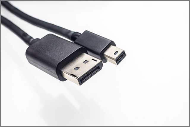
CHAPTER 7: Mini HDMI to VGA
A mini HDMI to VGA converter is a straightforward device that can convert from HDMI to VGA.
It allows you to use it with any VGA projector or VGA monitor.
Similar to conventional converters, this device needs no power source and utilizes the basic technique of ready-to-play.
This converter is ideal for laptops or PCs that require a short connection distance.
It’s easy to plugin, simple to use, and convenient for device conversions.
These cables also have reduced the risk of damage with shorter connections.
Conclusion
In conclusion, VGA output to HDMI converters is positive in today’s digital world.
Nowadays, you can find many electronic devices that can come with either port.
So, such converters can help you transmit signals without hassle or connection issues.
Not just that, but VGA output to HDMI converters is finally becoming much more widely accessible.
Some useful tips and tricks to remember include always setting your television’s image resolution to the ideal fit.
It will enable your converter to work effectively.
Contact proper professionals and experts in case of any issues.
Different companies provide different converters, but it is helpful to know the main features of your converter.
Hopefully, this detailed guide has given you a better understanding of the digital world.
Whether you’re looking for some media playing at home or quick conversion solutions at an IT department for your job, this article should fill you in with the best conversion solutions and options.