The insulation goes via two insulation paths – electrical resistance and capacitance. So, there shouldn’t be much leaking because of the impressive resistance levels. However, the problems occur due to wear and tear. The experts recommend limiting the length of the one-way feeder to 250ft. That’s because the capacitance goes up in long conductors, which increases leakage current. This guide reveals all about leakage current, which you might confuse with voltage leakage. You’ll discover ways to minimize its effects, so feel free to start reading now!
Get Your Free Sample!
Explore our custom services now. Email us at [email protected] for more details.
A Leakage Overview

Caption: A printed circuit board with electronic components
Leakage is any electrical energy transfer that goes over the accepted limits. The transfer always exists, and we assess it as insulation. Here are the common leakage examples!
Capacitors
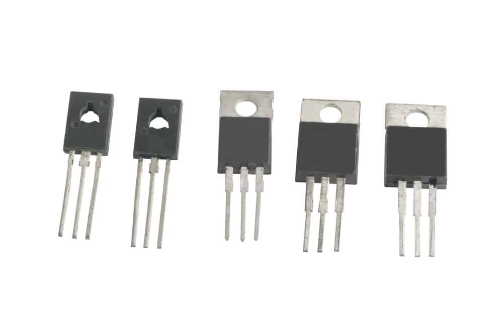
Caption: Power transistors close-up
You connect electronic devices to diodes or transistors. Those parts cause energy loss in the capacitor. On the other hand, diodes act as current conductors even when not in use. So, this current doesn’t have the same magnitude as when you turn on the device. However, you still notice the capacitor is discharging gradually.
Users could also face dielectric leakage. So, the material used for the capacitor isn’t an ideal insulator. It has non-zero conductivity, which allows current flow.
What if the current goes out of the circuit? If it leaves the predicted path, that can be dangerous. Apart from RF noise, it can lead to fires, electrocutions, and overall damage. So, it’s important to assess the situation and minimize the leakage effects. If it occurs in a high-voltage system, these hazardous voltages could have fatal consequences.
Semiconductors
A mobile charge carrier in semiconductor tunnels via an insulation area. As you increase that area, the leakage goes up, too. Furthermore, you can face a leak between the drain and source terminals of MOS transistors. We also know this process as subthreshold conduction. Depending on the amount of leak, it leads to performance problems or more demanding power consumption.
Did you know that leakage is what stops computer processors from delivering maximum performance? Manufacturers used different solutions but still failed to find an optimal setup. A defect in the production process can lead to increased leakage. So, the company needs to perform tests and find any issues.
Between Circuits and Electronic Assemblies

Caption: An electrical engineer worker
Is the desired current level zero? If yes, any current flowing there is a leak. So, that happens in turned off electronic appliances. Furthermore, it can occur in devices that or on standby. Although they want to draw the same amount of current, they still use a couple of microamperes. The problem is that it affects battery life, which can be an issue in portable devices. Therefore, manufacturers consider this unwanted current because it compromises battery duration.
If a circuit transfers unwanted energy, we consider that leakage. So, let’s say that the power transformer’s core doesn’t keep the magnetic lines of flux. If another circuit connects, it becomes a part of the leakage. Therefore, you could notice hums when using audio or other issues.
Now, let’s talk about an AC-DC power converter. You can use the main filters to secure power to the circuits supplying them. You have capacitors between the grounding and neutral or live conductor. So, you might face current leaking there. The acceptable amount is 30mA, although it can be even lower in medical applications. If excessive leakage current goes, it becomes a danger for anyone using the gear.
Get Your Free Sample!
Explore our custom services now. Email us at [email protected] for more details.
Leakage Current Measurement
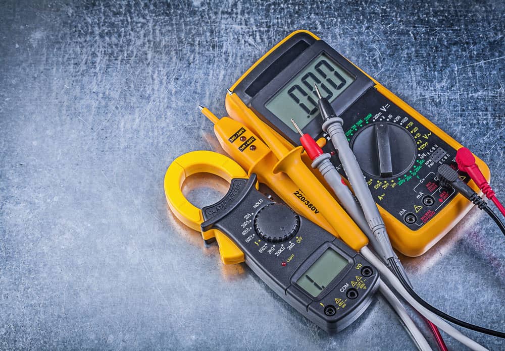
Caption: Digital clamp meter and electrical tester
On circuits protected by GFCIs (Ground Fault Current Interrupters), leakage current can cause unnecessary and intermittent tripping. So, how can you eliminate or minimize the effects? A clamp meter is a necessary tool. However, make sure the clamp meter is suitable for leakage current. Standard devices don’t register current under 5mA, and you need a unit with better performance.
How to Use a Clamp Meter with the Conductor

Caption: A person using a yellow digital clamp meter
Now, grab the current clamp meter and put the jaws around the conductor. Notice the value on the device. The experts suggest keeping the jaws clean for accurate results. Furthermore, keep the mating faces safe from damage. Finally, don’t let an air gap during the tests. Instead, close them together entirely. If you twist the jaws, that leads to wrong readings.
The device identifies the magnetic field around the conductors. If you test live conductors mixed into a circuit, the load currents will nullify each other. So, the leakage comes from another source. The measurements in these situations are often below 0.1mA, and you need the most accurate device you can find.
Here is an example of the 240V AC circuit. You disconnect all the loads and get leakage of 20mA (0.02A). According to Ohm’s Law, you divide the voltage with the current and get the resistance of 12M.
If you power down the circuit, you could get a 50MW or a higher result. The problem lies in the insulation tester. So, it uses DC voltage, but there’s no capacitive effect in the equation. The value of insulation impedance is the one under standard working conditions.
Suppose you connect monitors, computers, and other gear to the circuit, the result changes. That’s because of the input filters and their capacitance. Therefore, if you connect many devices, that increases the maximum leakage currents. You might face a GFCI trip if you add new gear to a circuit it’s protecting. That becomes a difficult issue to diagnose, especially if the GFCI trips randomly. What happens when the leakage current varies. Your leakage clamp meter should show changing or alternating currents during tests.
Assess the Leakage Current to Ground
The first thing to do is to connect the load. After turning it on, you’ll measure the current that includes leakages in that gear. So, the result should be acceptable. If it’s within a reasonable range, it means the circuit wiring leakage is lower. On the other hand, you can measure wiring leakage if you turn off the load.
Now, you can clamp the neutral conductor and phase. That will test the desired single-phase circuit. Therefore, the device will measure the current heading to the ground.
If you want to test a three-phase circuit, you need to clamp all conductors. Therefore, you’ll measure leakage current going to the ground. Make sure to include a neutral if you notice it.
Check the Ground Conductor to Measure Leakage Current
This is another easy way to measure leakage current. Use the clamp meter and put the clamps around the ground conductor. Make sure that you have the desired ground connection. Check out the leakage flow and see if it’s in an acceptable range.
Check the Unintentional Paths and Measure Leakage Current to Ground

Caption: An electrician examining a fuse box
You can clamp neutral/phase/ground together. Thanks to that, you’ll notice any imbalance current. So, it discovers current leaks in an electrical panel or outlet. You might have an undesired path to the ground. A common example is a concrete base where you put the panel.
So, check if there are other bonding connections. Is there a bond to a water pipe? If yes, that also causes an imbalance current.
Where’s the Leakage Current Coming From?
Tracking the source of leakage current can help to reduce or eliminate it. Any measurements you perform should lead you to the source and the complete system leakage. From there, you can see if you can make any improvements.
Line Leakage Test

Caption: An electrician testing a machine
Although many experts use this name, it’s actually a current leakage test. This measurement is done during the electrical safety test of a device. The idea is to find any leakage current over acceptable limits. That current can go via the capacitor’s dielectric or the insulation surface. Ideally, the current leaking from the power supply unit should flow through the ground connection and into the installation’s earth ground.
Generally speaking, the standards are more stringent in medical applications since weak patients are more vulnerable to electric shocks, which can be fatal. You need at least 100% of the input voltage. Try not to exceed 110% of the rated value for your system.
If you are a professional electrician, you know the importance of a visual check. So, start by assessing the setup. Your goal is to find any cracks or breaks in the components. Additionally, look for components put in the wrong place or any overheating and overloading issues.
Dead Electrical Testing
After visually inspecting the system, it’s time to perform electrical testing. You’ll need test meters, and you begin with dead tests.
This series of tests include:
- Continuity. So, start by checking if any wires or conductors have bad connections.
- Polarity. The polarity test confirms the sequence of the connection is optimal.
- Insulation resistance. Any material around the conductors should be in optimal condition.
- Earthing arrangement. First, check if the connections are of optimal quality in the electronic assembly. Next, the setup should meet relevant standards and regulations under normal operation.
Live Testing
This is the final part of the line leakage testing, and it contains two components:
- Earth fault loop impedance. What if a fault happens? If it does, the setup should disconnect the supply within the set time limit. So, your goal is to check this fail reaction is optimal.
- RCD. If there’s electricity missing, the system’s RCD component should react. So, this could happen if the system shocks a person. The electricity will go to earth through his body, which means it leaves the system. The RCD should detect this and act accordingly.
Conclusion
So, you can see, it is leakage current, not voltage leakage. And, the experts suggest that the maximum leakage current should be 210mA in any custom cable assembly. It can be a serious problem if you don’t keep it in acceptable ranges. At Cloom, we provide help with cable assembles, so don’t hesitate to contact us if you have any questions!
Get Your Free Sample!
Explore our custom services now. Email us at [email protected] for more details.