Whenever any fault or electrical surge occurs in many substations, the earth absorbs all the fault current. Even while providing electricity for domestic usage, the electricians ensure a proper grounding system to maintain the flow of electric current.
However, for setting up the earth system, you need to have enough soil corrosivity. How can you determine that? By conducting soil resistivity testing through sound equipment.
Get Your Free Sample!
Explore our custom services now. Email us at sales@wiringo.com for more details.
What Is Soil Resistivity Testing
The soil resistivity testing method tests how much current a specific volume of soil can resist. You can apply this test to determine the conductivity of the sample soil. Units to measure the soil resistance are Ohm-meter or Ohm-centimeter.
The soil Resistance test is one of the critical factors when deciding the electrical grounding design, whether you have a simple electrical design, low-resistance grounding system, or complex systems involving Ground Potential Rise Studies (GPR).
What Influences the Soil Resistance?
Nevertheless, it would help to keep the soil composition, temperature, and moisture of a specific place in mind as critical factors affecting soil resistance. Even if you look into the same place, you will find that the soil conductivity is changing as you move some steps away. In addition, resistivity may vary with the different soil depths and geographical locations.
You may also notice that as the seasons change, so as the moisture content of the soil. Due to the nature of soil layers and the water depth, the wetness level of a part of the earth varies. As soil and water level are more stable in the deeper strata of the earth, most experts recommend placing the ground rods as deep as possible in the ground. Moreover, they also recommend checking the stability of temperature first and then install the ground rods.
Get Your Free Sample!
Explore our custom services now. Email us at sales@wiringo.com for more details.
Major Applications of Soil Resistance Testing
You can test the soil and then use these soil resistivity measurements for the following applications.
Grounding Grids
If you deal with expensive machinery like those in an electric substation, you will use grounding grids for protection. Even the National Electric Code of every country sets specific grounding resistance requirements. For example, have a particular number of grounding rods installed in a substation.
Without that, the whole system is vulnerable to lightning. Grounding rods also lead to any fault current so that it does not harm a person nearby the station.
Cathode Protection
To protect the underground infrastructures like steel pipes you have installed underwater and want to protect it from rusting, you can use Cathodic protection.
There are two methods to choose from, Passive Protection and Impressed Current Cathodic Protection or ICCP.
- Passive Cathodic Protection: For this technique, you will attach a current zinc electrode to the system. As time passes, zinc will rust as it will attract all the oxidizing molecules to itself, and your system will remain safe.
- Impressed Current Cathodic Protection: The ICCP technique is more complex than the former. In this method, you will inject Direct current into the ground by a grounding structure or anode, and the current will pass from the anode through the land to the protected system.
For choosing the correct technique for cathodic protection, you first have to test the soil resistivity. In this way, you can design your protection scheme per your requirements.
Soil Resistivity Testing Techniques
For new installations, you have to look for a location where the resistance in the soil is the lowest possible. Practically, you can overcome these poor soil conditions with the help of advanced techniques.
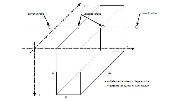
Four-pin Wenner Method/ASTM G57
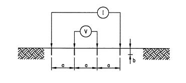
The Wenner 4-pin Method is the standard technique you can opt for testing the resistivity measurements. For this method, you will place four soil pins into the soil surface at an equal distance. Then you will inject a current of known value on the outer current probes and record the voltage signal between the inner probes.
Suppose the depth of current probes is less than probe spacing, as it usually happens. In that case, you can calculate the resistivity as follows.

Where
ρE = measured soil resistivity (Ωm)
a = soil pins spacing (m)
V/I= Wenner Resistance (Ω)
Using this method, you can increase the electrode spacing in the same path and measure greater soil depths. As the probe spacing increases, the source’s current penetrates a larger area horizontally and vertically. It is regardless of the changing soil conditions that result in distortions of the current path.
Lesser is the electrode spacing; shallower are the measurements from which you can check the soil conditions. With these measures, you can check the soil condition of the core locations where you will place your system.
Similarly, more significant is the probe spacing; deeper are the measurements. With these values, you can check the maximum area a system can cover for grounding. It is better to increase the range of probe spacing to assess the resistivity from different perspectives.
Schlumberger method
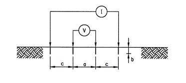
The Schlumberger method is another popular four-pin method to test the soil’s electrical resistivity. So, you will follow the same steps to set up the equipment for the Wenner method. The only difference is that the inner probes will now have different spacing than their distance from outer probes.
If the depth of pins b is lesser than distance a or distance c, you can calculate the resistivity as
Where
ρE = measured soil resistance (Ωm)
a = inner electrode spacing (m)
b = depth of the electrodes (m)
c = outer electrode spacing (m)
V/I = Schlumberger Resistance (Ω)
When the configuration is a>c, you will say it as the Schlumberger-Palmer Method. On the other hand, if the format is c>a, you will say it as “Schlumberger Method” only.
As you compare the Wenner and Schlumberger methods, you will notice that Schlumberger is less laborious. As, here in the latter approach, you don’t need to change the potential probe’s position and depth again and again to measure the resistance. In the Schlumberger method, you will need short cables, less free space, and even less time to check the voltage drop during the soil resistivity test.
Additionally, the c>a configuration requires sensitive measuring instruments. In contrast, a>c soil resistivity testing method is easy with greater values of resistance.
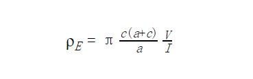
Conversion
Whether you are using Wenner or Schlumberger method, both relate the distance between the current probes to their depth. To convert between the values you calculate by these methods requires an approximate way.
If you calculate the soil resistivity using the Schlumberger method, assuming that the a=L/3, then the Wenner resistivity is as follows

where:
RW = equivalent Wenner resistance (Ω)
aW = equivalent electrode spacing with Wenner method (m)
aS = electrode spacing between inner voltages probe with Schlumberger method (m)
c = electrode spacing between outer probe with Schlumberger method (m)
You can use the Wenner soil resistivity testing method for measuring soil resistance. Using the Schlumberger method, you could measure the increased voltage signal with less sensitive instruments.
Although you conduct these methods with attention to detail, you may still find that any conducting objects in the soil near the soil pins may affect the diagnostic factor. Besides, a sensitive measuring setup may get different readings from the actual as the earth ground stakes have external interference. For better readings, you have to check for other current paths crossing your location.
How to Conduct a Wenner 4-point (or four-pin) Test in a Real Setup
Good soil quality can help you create an adequate grounding. For that, you need to have accurate measurements of soil resistivity values.
Preparation
For conducting the Wenner Four Pin test, you first need to space out four soil pins at equal distances. Typically, you can space them by 1, 1.5, 2, 3, up to 10 inches distance. As for the depth, you can go as deep as 5 inches in the earth’s surface for basic measurements.
The same is valid if you place the probe 40 inches inside the earth’s surface. That way, you will measure the resistance along with this depth, including all the points from the start to the end of the pin. Thus, to process the raw data, you can use computer software and determine the resistivity value.
Procedure
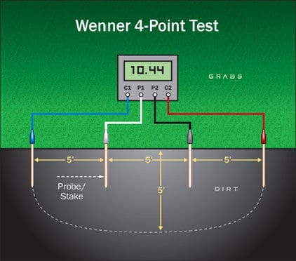
As the above diagram shows, insert probe C1 on the edge of the area where you have to measure the resistance in soil. Then, you will insert the probes P1, P2, and C2 on a space of 5, 10, and 15 inches, respectively, in a straight line. This way, you can measure the soil resistivity from 0 to 5 inches deeply. Note that the C1 and C2 are the outer probes, whereas P1 and P2 are the inner probes of the testing setup. Apply Ohm’s law to measure the resistance.
For the next set of measurements, you can move away from the probes from C1. For example, to test 10 inches in depth, move the P1, P2, and C2 10, 20, and 30 inches away, respectively. Continue moving away from the C1 and calculate sets of measurements. Keep in mind that numerous factors affect the resistivity on soil depths, be it soil classification or quality.
Data Analysis
You can use the following formula to calculate the soil resistance in ohm-meters as you have collected the data.

Where
ρa = Resistivity
B = Depth of probes
A = Spacing of Probes
R= Resistance from the meter
Things to Consider When Conducting Soil Resistivity Testing
While you are testing the resistivity in soil, certain factors affect the measurements. Some of them are:
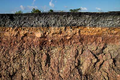
Layer Effects
You can divide the earth into layers. When you are testing for the Cathode protection, you calculate the total resistance of all the coatings. So, to check the resistance on that layer, where we have to place the cathode, you have to make some adjustments and subtract the resistance of the upper layers.
One method for this cause is the Barnes method, assuming that there are solid layers of equal thickness. Hence, you will take the resistance values, change them into conductivity and see it for each layer. Then you will convert the conduction back to resistance and finally calculate the resistivity using the Werner method. The table for 60m depth to 200m depth is as follows.
| TEST DATA | BARNES ANALYSIS | ||||
| Spacing a (m) | Resistance (ohms) | Conductance 1/R (Siemens) | Change in Conductance (Siemens) | Layer Resistance (ohms) | Layer Resistivity (Ohm-m) |
| 20 | 1.21 | 0.83 | — | 1.21 | 152 |
| 40 | 0.90 | 1.11 | 0.28 | 3.57 | 449 |
| 60 | 0.63 | 1.59 | 0.48 | 2.08 | 261 |
| 80 | 0.11 | 9.09 | 7.5 | 0.13 | 17 |
| 100 | 0.065 | 15.38 | 6.29 | 0.16 | 20 |
| 110 | 0.058 | 17.24 | 1.86 | 0.54 | 68 |
Testing Equipment
There is a lot of electrical noise on the earth due to railway tracks, power lines, etc. Moreover, it can distort the actual readings. For that reason, you need specialized meters with advanced electronic packages to remove disturbance. You will come across these two types in the practical environment.
- High-frequency Soil Resistivity Meters that work above 60Hz and collect data in 100ft deep soil. These are less expensive and commonly used equipment.
- Low-frequency Soil Resistivity Meters work in 0.5 to 20Hz and collect data in deeper soil as companies design them to support large probe spacing. Besides, these are expensive as they have advance filtering packages. Thus, you can use them when installing the anode deeper than 100ft.
Field Data
In terms of the field in which you are testing, consider these practices and avoid erroneous data.
- Choose the suitable test area for the Werner method as you will require to space the pins wider as you check the resistance in depth.
- Avoid the presence of any conducting material near the testing location. For that, check for the pipes and metallic objects beforehand.
- Insert the probes properly for your intended test type.
- Avoid areas with higher electrical noise, such as electric rail systems.
- Record the test location and soil conditions accurately to avoid enormous consequences in the future.
Conclusion
Soil Resistivity Testing is vital to protect the grounding grids and systems. The factors such as moisture, high electrical noise may affect it. Still, you can have accurate readings as you implement proper testing methods.
Here at Wiringo, we offer custom wiring assembly with attention to each detail so that your test wiring gives you accurate measurements.
Get Your Free Sample!
Explore our custom services now. Email us at sales@wiringo.com for more details.