Some, if most people are intrigued, by the workings of different equipment and machinery. If you fall into this category, then you are at the right place. In this piece, we will focus on some of the basics of the rotary encoder pinout. Let’s get started!
Get Your Free Sample!
Explore our custom services now. Email us at sales@wiringo.com for more details.
What Is A Rotary Encoder?
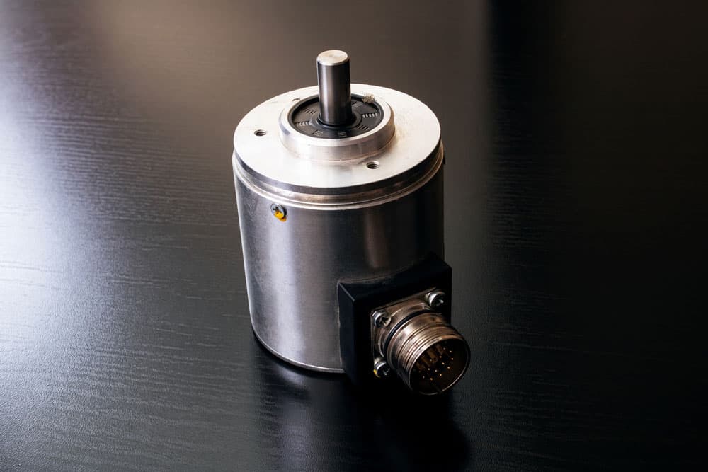
A rotary encoder is an electro-mechanical device that measures and converts an axle or shaft’s angular motion and position to either digital or analog signal outputs. There are two main types of rotary encoder pinouts. These are the absolute rotary encoder and the incremental rotary encoder.
Absolute Rotary Encoder Pinout
An absolute rotary encoder, also known as a parallel absolute encoder, has its output indicating the current shaft position. And this makes it an angle transducer. An absolute rotary encoder maintains position data and information even without power.
The encoder has multiple rings with various weightings that provide the data and information. The encoder’s absolute position is represented within the range of one complete revolution. This encoder can be broken down further into the different types of absolute encoders available. They include:
- Mechanical encoder.
- Optical encoder.
- Magnetic encoder.
Incremental Rotary Encoder Pinout
Incremental encoders, on the other hand, provide data and information on the position immediately. This encoder does not give any report or keep track of the absolute position.
If you have to use an incremental optical encoder for the absolute position of your mechanical system, then you have to home it. Homing refers to the moving of the encoder to a fixed reference point. Doing this will initialize absolute position data and information.
Rotary Encoder Pin Configuration
A rotary encoder module has a total of five pins. Three of these pins are for the rotary encoder, while the remaining two are for the button switch. To give you a better perspective of a rotary encoder pin configuration, we will be using the M274 pinout as an example. With this rotary encoder module, four pins are compulsory.
The pins below Contact A or DT and Contact B or CLK measure the direction and axis movement.
| Pin Name | Description |
| GND | Connected to GROUND |
| + | Connected to +5V |
| SW | The output of the internal button |
| DT | Contact A result or DATA |
| CLK | Contact B output or CLOCK |
How Does A Rotary Encoder Work?
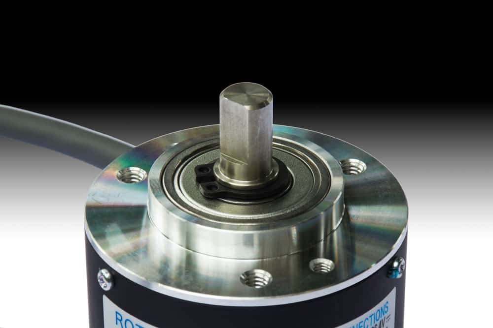
Direct closeup of a rotary encoder
If you were to open up a rotary encoder inside, you would find a slotted disk connected to pin C, the common ground pin, and contact pins A and B. Once you turn the knob, pins A and B come in contact with pin C.
This order depends on the direction in which you will be turning the knob. Once the pins come in contact, they produce signals that are shifted 90° out of phase with one another. The result of this is quadrature encoding. Quadrature encoding is when one pin comes in contact before the other.
Using a tracking system to determine which pin comes in contact first and which one disconnects from the ground, you can determine the direction that the knob is rotating.
Get Your Free Sample!
Explore our custom services now. Email us at sales@wiringo.com for more details.
Rotary Encoders Vs. Potentiometers
Before we look at some of the aspects, these two differ on what they have in common. Let us define a potentiometer first.
A potentiometer is a three-terminal resistor that comes with a rotating contact. This contact forms an adjustable voltage divider. Knowing what we know about the rotary encoder telling these two apart is easy.
The differences between a rotary encoder and a potentiometer include but are not limited to:
- Potentiometers are analog controls with a range of 0 to 100%.
- The position of the potentiometer is always clear.
- Encoders are inherently digital, especially increment encoders.
- Positions registered by increment encoders require constant monitoring.
How To Connect A Rotary Encoder To Arduino
Now that you understand how a rotary encoder works, you may be looking forward to tinkering with one to put your newly acquired skills to the test. If you want physical control over your electronics, you should consider experimenting with a rotary encoder and Arduino.
Rotary encoders offer a better alternative to push buttons or touch screens, especially where knobs provide a more intuitive solution for your different applications. Here is how to connect a rotary encoder to an Arduino.
Requirements
- Arduino Nano
- Encoder module
- USB A to mini-USB cable
- Black wire and red wire
- Breadboard
Rotary Encoder To Arduino Connection
If you already have an encoder with a PCB, you will have the following pins GND, +, SW, DT, and CLK. In some cases, the naming of the pins might be different. In this case, make sure that the GND pin connects one center encoder pin and one switch pin to the ground.
The + pin pulls up the encoder output signal towards the positive power rail through the soldered resistors. The SW pin is the second pin of the shaft switch. CLK and DT are the two encoder pins that will generate pulse outputs when the shaft is rotated. With your black wire and red wire completing the setup, you can get started.
The Code
Once your setup is complete, it is time to write some code. For this, you need to use the PlatformIO IDE. For this example, you will only use the encoder pins. The button state will read without the integration switch.
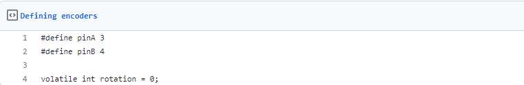
Defining Encoders
Before you jump into the coding process, you need to define the encoder pins. The variable rotation defines the direction the shaft will turn. In the example above, the probable values are -1. The direction stated by -1 is in one direction of rotation, 0 for stationary, and 1 for another direction.
Defining Encoders
Interrupt Function

Interrupt Function
To avoid missing a falling encoder output edge then you need to use interrupt.
With the Arduino nano board, you use only 2 and 3 pins for the external interrupt pin source. The first line of the rotary() function checks whether the status of pin A is low. If this function runs when there is a change interrupt on the pin, it means there is a falling edge.
The line if(!digitalRead(pinB)) checks the status of the send encoder pin. If it is Low, the knob is turning in one direction (sets rotation = -1), and if it is high, the rotation is set to 1. There is no exact way to determine the direction of rotation except through trial and error.
With that complete, it is time to fill the setup() function.
Setup Function
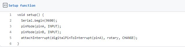
Setup Function
The first line of this code initializes the Serial interface. To the encoder, pins are set up and connected as inputs. Lastly, PinA is set and assigned the interrupt function. Once there is a changing edge on PinA, the interrupt runs a function called rotary.
Void Loop Function

Void Loop Function
To check if there was any change in the rotational speed void loop function is used. When the rotation recorded is nonzero, check the value of the rotation variable. If it is 1, the code will print out to the serial interface string “LEFT”. If it is -1, then the printout will read “RIGHT”. Lastly, the rotation will reset to zero.
Results

Complete Code
Once you are done with the code, press the upload button and turn the knob on your setup. You should be able to read the printout on the serial monitor.
Applications
- Engineering systems.
- Hobby projects.
- Industrial machines.
- Measuring instruments including angles with encoders measuring.
- Motors
- Robotic arms
- Security systems.
- Systems like CROs and signal generator
- Vending machines.
- Air handlers cranes.
Conclusion
With everyone rushing to develop systems, appliances, and gadgets that rely primarily on touch screens, knobs do not seem to be going away anytime soon. The use of rotary encoders is evident in industrial systems, appliances, and tools.
Rotary encoders, although simple looking, are part of a complex system at any given time, depending on the use case.
If you are looking to dive further into this topic, you can always contact us.
Get Your Free Sample!
Explore our custom services now. Email us at sales@wiringo.com for more details.