Every circuit breaker has a trip unit to protect the device upon detecting overcurrent. Trip units allow accommodation of load circuit and use field interchangeable rating plugs. However, these units may become faulty, and overcurrent protective devices may fail. To maintain the reliability and safety of such systems, you must execute well-planned injection tests in these air circuit breakers.
Get Your Free Sample!
Explore our custom services now. Email us at sales@wiringo.com for more details.
Injection Testing for Circuit Breakers
Many electricians use injection testing to check the characteristics of protective devices, including protective relays, power transformers, etc. For the circuit breakers, you can make use of the same injection test sets. You will conduct this test regarding tripping time, insulation capacity, resistance, operational behavior, etc.
There are two types of commonly done Injection Test sets.
Primary Injection Testing
Primary current injection testing is a detailed system analysis that takes time. You can test solid-state and electromagnetic trip units through a primary injection test. In addition to trip units, you can test a low-voltage circuit breaker through this method. It can verify that you have connected the sensors and wiring properly.
Though it is a beneficial method, it has one major drawback. You can test only one phase at a time and detect no polarity problems. You have to test all the wirings separately with the Polarity Test.
However, primary injection testing also requires more money and is an expensive maintenance program. The price is because it used large testing equipment, time-consuming single-phase tests, and proper circuit breaker removal. Therefore, the maintenance prices go up when all these steps are incorporated.
In most cases, you must occasionally follow the primary injection test sets with a secondary one.
Secondary Injection Testing
On the other hand, you can only conduct the secondary current injection test on the solid-state trip units. Hence, you cannot perform this test on molded case circuit breakers or older ones. In secondary current injection testing, you inject a three-phase current into the trip unit. This allows you to verify the trip unit polarities at the same time.
However, one major drawback of this testing is that you can inspect only the trip unit logic and the system’s wiring. Unlike primary tests, you cannot check all the current-carrying components simultaneously. This fact gives an edge to the primary injection test sets over the secondary one.
Suppose either test fails and you detect anomalies in the functionality. In that case, you have to change the trip unit as soon as possible and mark it as defective.
Why Do We Need Primary & Secondary Injection Tests?
Due to the following reasons, you may want to use Injection Test Sets over a specific period.
- For personal protection, It is vital to maintain the trip unit logic. If the device cannot trip within the given time, it may cause arc flashes and electrical fires. As a result, it may damage your assets, and your life will be in danger.
- For device protection: Again, if the device cannot trip within a given time, it will damage the equipment downstream more than you expect.
To avoid these events from happening, you have to conduct the current injection method. That way, your electrical devices will give you a good performance in the long run.
How Do Primary Injection Tests Work?
For a successful test, you must appropriately determine a number of factors.
Input Specifications
The output of a primary injection test depends on the input voltage. The input voltage must be within +_5 % of the test specifications. You must appropriately size the input breaker because there are higher losses since the test is done at higher currents.
Therefore, the relationship between the output and input current for primary injection tests is exponential. When performing a high current test, installing an input breaker capable of handling the input power needed for max test currents that you plan on applying as you test the breakers is essential.
The connection between the input voltage terminals and the input voltage supply on the test must also be short in length and appropriately sized. Excessively long connections could result in voltage drops at the input voltage terminals, affecting the test’s effectiveness.
Test Connections
Since high-current tests have extremely low open circuit voltage (5V – 10V), the max output from a high current is limited by the circuit’s impedance, which mainly depends on the test connections. The connection is normally done using cables for breakers with a lower amperage. The cables should have sufficient ampacity. You can achieve this by connecting some cables in a parallel manner. It’s best to use as short cables as possible. To further minimize the impedance of the circuit, you can twist the cables together.
Higher current tests for draw-out circuit breakers typically use stab sets for connections to ensure the circuit impedance is negligible. You can create various designs of stab sets to use with different circuit breakers.
To deal with high circuit impedance when testing at lower currents, you can utilize a modular design that connects many high current sources in series to get a higher open circuit voltage to push your desired current through your breaker.
DC Offset
During an immediate trip test, an error can occur in the results due to a DC offset in the current pulse.
The unbalanced nature of the first few current cycles occurs due to a high X/R ratio in inductive circuits. You can minimize the DC offset by automatically or manually adjusting the point on the voltage wave where the output is energized (firing angle). The DC offset is measured by the difference between the RMS and peak/√2.
For a perfectly sinusoidal wave, the two values should be equal.
Ground Fault Protection On Trip Unit
When testing circuit breakers with trip units featuring ground fault protection, it’s important to turn off the ground fault protection to be able to run other tests. The current involved in other tests is often higher than the ground fault pick-up. While some trip units offer the option of turning off the ground fault protection, not all do.
However, you can still test by injecting current through 2 poles connected in a series.
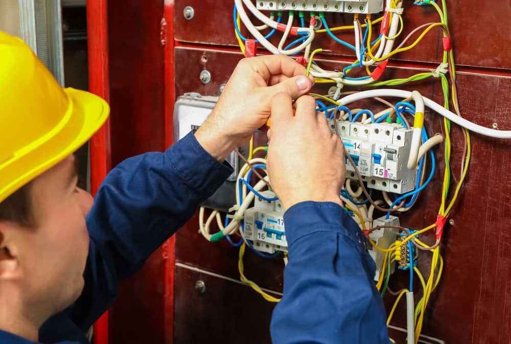
Caption: Circuit Breaker
Get Your Free Sample!
Explore our custom services now. Email us at sales@wiringo.com for more details.
Primary Injection Test Modes
You can choose different injection test sets according to the functions you are testing. For instance, you will use long-time and short-time delays to test the circuit breaker’s overcurrent protection features.
Long-time delay and pickup
The feature of long-time delay provides overload protection. For this, you will set the pickup time according to the continuous current rating.
Then, you will inject the test current that is three times the long-time pickup. Moreover, apply the current from each pole and record the trip time.
Record the results and create a time-current curve out of the found data. Compare the readings with the data manufacturers have provided.
If the values you found are near the standard ratings, you are good to go. Otherwise, you have to replace the equipment.
Remember, you will record the trip time in seconds.
Short-time delay and pickup
The short-term delay feature protects the equipment from short-circuiting or any other faults provided by an intentional delay.
Here, you will inject a test current 1.5 or 2.5 times of short-time pickup, multiple long-time pickups. Moreover, apply the current from each pole and record the trip time.
Next, compare the readings with the data manufacturers have given in the manual. Record the results and create a time-current curve out of the found data. In this case, you will record the trip time in milliseconds or cycles.
Instantaneous pickup
The instantaneous trip feature also protects the equipment from short-circuit or fault conditions. Still, you do not need to provide any time delay. In this test, you will inject instant current pulses with increasing magnitude. Apply the current from each pole until the circuit breaker trips.
You will keep the starting pulse on about 70% of the expected pick-up and record the value when the circuit breaker trips. In this case, manufacturers typically provide tolerance of about 10% to 25% on the pickup.
Ground-fault delay and pickup
The ground fault pickup protects against ground faults. Here, you will inject a test current 1.5 or 2.5 times the pickup. Additionally, the test current is a 20-60% fraction of the continuous current rating value.
In a real environment, you will perform this test for service entrances by the National Electrical Code (NEC).
How Do Secondary Injection Tests Work?
Primary injection test and secondary injection test sets work identically to each other. For both electrical tests, you will inject the calculated amount of current through the breaker. Next, measure the time it will take to trip the breaker.
Secondary Injection Test Modes
You can perform secondary injection tests on electronic trip devices and solid-state trip units using different test modes depending on your desired accuracy and outcome of the test.
No Trip Mode
You can test the protective features of an electronic trip device; however, it won’t send a trip signal to the breaker’s trip actuator.
You can perform this test while the breaker is energized and conveying load current since a no-strip test will not cause the breaker to open.
Trip Mode
The protective functions of an electronic circuit are tested similarly to the no-trip test. However, the trip unit will signal the breaker’s trip actuator.
Therefore, the circuit breaker will open, so trip mode tests are normally done only when the circuit breaker is removed from its compartment, meaning it’s disconnected from the switchgear bus.
Self-Test Mode
Some modern protective relays and solid-state trip units feature integrated self-test functions that don’t need a separate test kit.
Tri-unit self-tests are undoubtedly easier to perform than other tests and can be done more frequently.
A trip test is ideally suited for troubleshooting a suspected breaker malfunction.
Similar to secondary current injection tests, the self-test functions don’t verify the performance of the circuit breaker sensors and associated current wiring.
Additionally, some components of the trip unit that convey secondary current can’t be functionally tested with self-test.
Hence why occasionally self tests are accompanied by secondary injection tests or primary injection tests.
Most modern solid-state trip units constantly execute self-diagnostics checks. Then, any potential issues with the trip unit are normally signaled by a displayed fault message or status lamp.
Also, the trip device might be able to communicate its fault condition or alarm through a digital communication system or built-in relay contact.
Primary vs Secondary Injection tests: Differences and Similarities
| Differences | ||
| Primary Injection Test | Secondary Injection Test | |
| Application | Primary injection tests are performed during the maintenance and commissioning or after modifications as functional tests of the whole system. | Secondary injection tests can only be used during maintenance programs for a solid-state trip unit. |
| Shortcoming | Primary injection testing might not detect polarity issues and sensor wiring. All 3 phases of the circuit breaker must be tested simultaneously. | With secondary injection testing, only the solid-state trip unit components and logic are tested. |
| Functions | Primary injection testing is the only way to confirm the proper installation and operation of the entire protection chain. The tests entail the whole circuit: trip circuits, alarm circuits, circuit breakers, the current transformer secondary and primary, and all the wiring. | Unlike primary injection testing, secondary injection testing doesn’t verify the wiring circuit breaker current conveying components or current sensors. |
| Test Set | Test sets are available in different sizes depending on the output range. Test sets for testing power circuit breakers are normally heavier and larger. | A test specially designed for the device intended for testing. |
| Similarities | ||
| Purpose: | Verify the proper functioning of a circuit breaker trip unit during startup and maintenance inspections. | |
Conclusion
As the breakers may be magnetic or thermal, you will perform some electrical tests. However, the method will differ slightly. You can choose primary injection test sets or secondary inject test sets. Both to test the trip functions of the breakers. Here at WIRINGO, we offer custom wiring assembly with attention to each detail so that your wiring is easy to check and maintain.
Get Your Free Sample!
Explore our custom services now. Email us at sales@wiringo.com for more details.