The introduction of flexible PCB technology resulted in innovation in electronic gadgets. You may be surprised that even laptops and smartphones also use this technology. In this blog post, let’s read about myths about flexible PCB assembly.
Get Your Free Sample!
Explore our custom services now. Email us at [email protected] for more details.
What are flexible PCB assemblies?
Flexible PCB assemblies refer to mounting components on the surface of the flexible printed circuit board or flex boards. They require thin laminates in their manufacturing. Manufacturers cannot assemble them directly on SMT lines as rigid circuit boards. First, these flex boards need to be fixed on some rigid career to be treated like rigid PCBs.
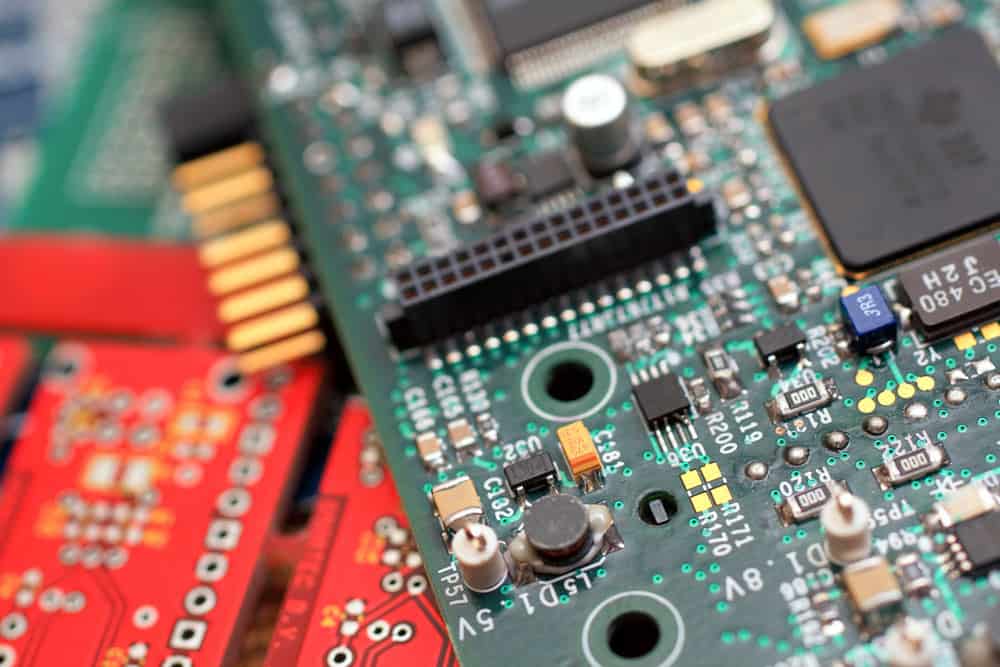
Caption: PCB
Flexible PCB assembly properties
Compared with rigid board assemblies, flex board assemblies have the following properties.
Flexible nature
The assembly of flexible printed circuit boards and their soldering is unlike the assembly of rigid PCB boards due to the flexible nature of flex PCBs. It is essential to use a special carrier board for flexible PCB assembly for fixing, transmission, and completing the surface mounting of the components.
Low density
Manufacturers use flexible PCBs for some module connections. As a result, the circuit density on the flexible PCB is relatively low. The number of electrical components remains under 50, and some flex boards only have as few as two connectors.
A large number of panels:
Miniature electronic devices like smartphones and digital cameras make maximum use of flexible PCBs; thus, the board size is small. As said above, the number of components in the flex circuits board is also low. Therefore, to improve the efficiency of the PCB, manufacturers use panels for assembly, which are later separated through punching.
Wide application of auxiliary fixtures
The flexible PCB assembly process uses many institutions as it damages and deforms easily. These fixtures include a board carrying tray, PCB baking fixture, function test fixture, cutting fixture, and electrical test fixture.
High-quality product requirement
Components must meet application requirements because flexible PCBs are mainly sued in applications requiring repetitive bending and accuracy. Thus, it is essential to maintain cleanliness, have soldering reliability and take antistatic precautions.
High assembly cost
As the Flex PCB assembly process needs different fixtures, a low rate of equipment utilization, high accessories demand and longer manufacturing time, and higher standards for product quality, the assembly cost goes high compared to rigid PCBs.
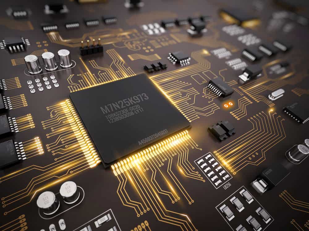
Caption: high tech electronic PCB
Get Your Free Sample!
Explore our custom services now. Email us at [email protected] for more details.
Design consideration of Flexible PCB assembly
The three crucial flexible PCB specifications include:
Material of Flexible PCB:
The materials you need to manufacture the flexible PCB include a metal conductor layer, adhesive, substrate material, and cover layer. The primary material is the flexible insulating film, which acts as a carrier with superb electrical and mechanical performance. Other ordinary materials include polyimide film and polyester, from which polyimide film is most common. Other substrate materials, such as thin FR4 and PEN, are also included.
Structure of flexible PCB:
You can classify flexible PCB into these different categories:
- Single-sided flexible PCBs have a simple structure and are very easy to fabricate.
- Double-sided flex PCB has a more complicated structure than single-sided PCB, and thus you may face more control difficulties.
- Multi-layer Flex PCB has the most complicated structure as it has more than two layers. It becomes more difficult to control its fabrication quality.
- Single-sided rigid-flex boards.
- Double-sided rigid-flex boards.
- Multi-layer rigid-flex boards.
Bend radius:
The bend radius of flex PCB varies typically between 5mm to 11mm.
Flexible PCB assembly process
The flexible PCB assembly process’s success depends on the board’s consistency, position accuracy, and flatness. Here is the process of the flex circuit assembly.
FPC pre-treatment
The FPC board tends to absorb moisture during transportation and storage. If manufacturers do not extract this moisture, it will vaporize during reflow soldering and protrude from the FPC board in the form of water vapor. To avoid this situation, FPC boards go under baking at a high temperature of around 80-100°C for about 4-8 hours. Sometimes, the baking temperature goes up to 125 degrees Celsius, but manufacturers must shorten the baking time. Generally, experts advise not to stack the FPC too much, and 10-20 PNL is more than enough.
Sometimes, manufacturers also put a piece of paper between each PNL to ensure isolation between different layers. Makers ensure that FPC does not undergo discoloration, warping, deformation, or other defects. They put it into line only after IPQC qualifies it.
Production of FPC assembly fixture
After baking, manufacturers study the drilling hole layers of FPC to develop an FPC positioning template and carrier fixture. Makers ensure that the positioning template pin diameter is the same as that of the positioning hole on the carrier board and the hole diameter of FPC. FPCs may differ in thickness to protect certain parts of the section or for design reasons.
Thus, the carrier board and the FPC must follow a similar order process. The main aim is to keep the FPC flat during placement and printing. Further, it is also essential that carrier boards comprise light and thin material with low heat absorption, fast heat dissipation, high strength, and little warpage deformation. Common carrier material includes synthetic stone, silica gel plate, aluminum plate, etc.
Positioning of FPC:
Once manufacturers fix the FPC on the carrier board, the printing, soldering, and mounting time should be as little as possible. Thus, they ensure that FPC fixes on the carrier board accurately. There are two carrier boards, one with positioning pins and the other without.
The carrier board without positioning pins works with the one with positioning pins on the positioning template. To fix the carrier board on the template, first put the carrier board on the template so that positioning pins come out from the holes of the carrier boards. Now, put the FPC piece-wise. Now, fix the pins with the tape and remove the FPC board from the template to proceed with printing, soldering, and patching. Manufacturers fix the carrier board with the help of several positioning pins of 1.5mm in length, and they can put the FPC on spring positioning pins and fix them with tape.
While fixing the FPC board on the carrier board, manufacturers use single-sided tape so that FPC does not shift or warp. Here, the tape viscosity is moderate, so makers can easily peel off after the reflow soldering process. Sometimes, Assembly makers also use automatic tape machines to cut tapes of similar lengths to improve efficiency and to make them cost-effective.
Besides the above method, manufacturers sometimes use double-sided tape to fix the carrier board to the FPC.
FPC solder paste printing:
The solder paste composition does not matter much for FPC, and the metal or size only depends on the presence of the fine-pitch ICs. However, FPC does have special requirements for solder paste printing. The solder paste must be convenient to print, have excellent thixotropy, and be firmly attached to the FPC. The soldering flux printer has an OP system or optical positioning to improve printing quality. Despite a proper fixation of the FPC and carrier board, some gaps remain. Thus, set equipment parameters appropriately to get the best printing effect.
FPC assembly:
Manufacturers use high-speed placement machines based on the components’ number, product characteristics, and the efficiency of placement needed. Due to the optical marks on FPCs for positioning, the surface mount technology on FPC and rigid circuit boards remains more or less the same.
As mentioned above, there are always some gaps between the carrier circuit board and FPC. Hence, manufacturers ensure the accurate setting of blowing pressure; the suction nozzle drops its height and other equipment. You must also know that as FPCs are connected boards, their yield is always low. Thus, the complete PNL has some damaged PCS. Thus, the placement system should have a function for bad mark identification to enhance production efficiency.
FPC reflow soldering
Manufacturers use hot air convection reflow (infrared) so that temperature in FPC changes more uniformly, avoiding poor soldering.
Flex PCB Assembly Production Equipment
With the help of the equipment, production can be efficient.
Solder paste printer
The paste printers have plate loading imprinting, the addition of solder paste, and transferring circuits. To use it, fix the flexible board on the top of the printing table. Print the solder paste/red glue on the pad via stencil and left scrapers. Next, put a transfer station into the machine to place the components.
Pick and place machine.
In the production line, you may also know it as a mounting machine or surface mounting system. It is a form of a device that you place on a flex PCB pad. Manufacturers configure it once the solder paste printer is and use the placement head for mounting the surface components accurately.
Reflow soldering
A heated circuit heats the nitrogen and air in reflow soldering to generate high temperatures. The soldering on the components’ sides melts, creating a tight solder joint with the motherboard. Reflow soldering can easily control the temperature and avoid oxidation.
AOI detector
AOI, or automatic optical inspection, is equipment to detect common defects during welding production. Based on the optical principle, it is a newer technology that manufacturers are rapidly adopting. Now, you can also find AOI test equipment in the market.
During the AOI inspection, the equipment scans the flexible circuit assembly with the help of a camera, collects the images, and compares the junctions with the approved database parameters. Once the image processing is complete, it will mark the defects with the automatic signs or display. The maintenance personnel takes out the defective pieces for repair.
Component trimming machine
You can cut and arrange the components with the help of this machine.
Wave soldering
It can ensure that the board’s soldering surface is in touch with the high-temperature soldering liquid tin so that soldering occurs perfectly. The liquid tin creates a slope, forming a wave-like process with the help of a particular device. Here the primary material is solder bars.
Tin furnace
In electronic welding, the tin furnace is the welding tool. The tin furnace gives good welding consistency in discrete flex boards. The process is fast and easy and delivers high efficiency.
Cleaning machine
You can clean the flex circuit board and remove the residue after soldering with the help of this machine.
ICT test fixture
ICT test fixtures help test short circuits, open circuits, and welding conditions of different parts. Technicians use test probes to check the PCB layout’s test points.
FCT test fixture
This Functional test checks the flex boards in simulated working conditions and whether the tested PCB boards will work in different design states. With this, the manufacturers get the values of different states to confirm the unit under test.
Aging test frame
In this test rack, PCB assemblies are tested in batches by pretending the user’s operation for extended periods.
Conclusion
We would like to know how the flex PCB fabrication and assembling process is completed. If your application requires any help regarding the flex PCB and assembling service, contact Cloom. We design, manufacture, and customize all types of Printed circuit boards and wire harnesses to meet our customers’ every need.
Get Your Free Sample!
Explore our custom services now. Email us at [email protected] for more details.