Nowadays, electronic devices are present everywhere, whether it’s a commercial building or residential spaces. That means circuit breakers, switches, relays, and other electrical connections work around the clock to prevent electrical damage. However, as long as two conductors are in contact, you can expect some resistance. And too much resistance leads to power outages and other electrical emergencies. So regular maintenance is a must for these electrical connections. Well, that’s where a ductor test comes in; read on to discover more about ductor tests.
Get Your Free Sample!
Explore our custom services now. Email us at [email protected] for more details.
What Is a Ductor Test?
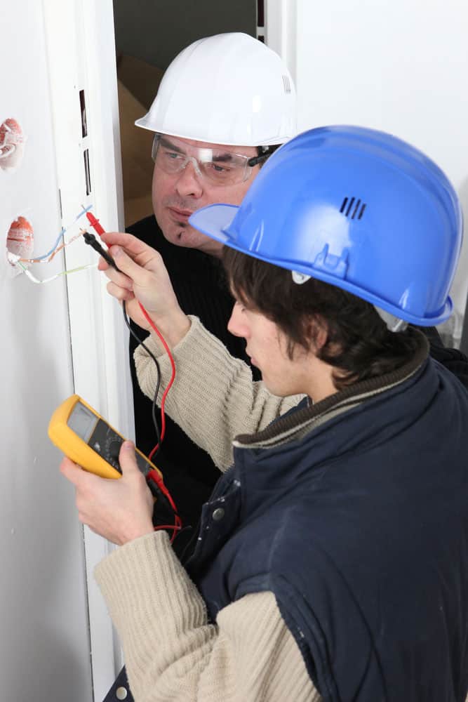
Also referred to as a contact resistance test, a ductor test involves measuring the amount of resistance detected in electrical connectors, such as cable connections, joints, and busbar sections.
Contact resistance occurs when an electrical device limits or opposes the amounts of current flowing through it. Alternatively, it can occur when contacts from different devices touch.
Contact corrosion, loose connections, or adequate joint tension may occur on electrical connectors. Furthermore, increasing resistance levels will reduce the current carrying capacity, which results in major outages, contact losing phases, or even fires. Luckily, contact resistance tests help you maintain an acceptable resistance level to prevent limiting current flow.
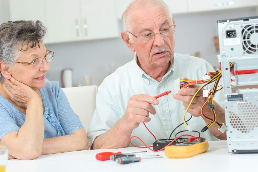
What Is a Ductor Tester?
You can conduct ductor tests using specialized equipment known as a doctor tester. The equipment is also popularly referred to as an ohmmeter. It will measure the electrical contact resistance in a single or complete circuit. The results appear in ohms, named after the famous German physicist Georg Simon Ohm.
The tester consists of a DC ammeter, one resistor, and a 3V battery or internal power source. Typically, they come in different sizes, depending on the level of electrical testing. However, these ohmmeters come in two distinct types: micro – ohmmeters, milli- ohmmeters, and mega – ohmmeters.
1. A series type ohmmeter
In this ohmmeter, the measuring resistance circuit connects to the meter in a series. It consists of 4 unique resistors that perform different roles. For example, R1 limits current flow, R2 is a zero adjuster resistor, RX is an unknown resistor, and RM is an internal resistor. It also features an internal battery voltage-E and two output terminals (A and B).
You can measure the contact resistance values through the D’Arsonval movement, which connects R2 in a series with R1 and the battery connected to outputs A and B. If the outputs are open circuits, no current will flow through, and the pointer will drift towards the infinity symbol, indicating infinite resistance. However, you can get varying resistance readings, depending on the connections.
2. A shunt type ohmmeter
In a shunt-type ohmmeter, the measuring resistance is connected parallel with RX and the battery. In addition, the meter is primarily helpful for measuring low-value current resistance. Usually, RM, R2, and E (the battery) are the most active components in a shunt-type ohmmeter. In addition, RX connects to outputs A and B.
But unlike the series type ohmmeter, the infinity symbol is on the right, and zero is on the left. Therefore, when RX is zero, the resistance reading becomes zero, but when the outputs are open, the circuit detection diverts to the infinity symbol to indicate infinite resistance. More importantly, you should also use a switch for this test to prevent unlimited current flow.
Get Your Free Sample!
Explore our custom services now. Email us at [email protected] for more details.
How to Determine the Ductor Test Criteria
The contact resistance test depends on several factors, including the type of connection (is it welded, clamped, or bolted?), contact pressure, and metallic surface area. However, these factors may vary depending on the equipment, contact material, or manufacturer’s preference.
There’s no code for minimum contact resistance, but the maximum contact resistance may differ from manufacturer to manufacturer. For this reason, you should always consult the manufacturer before running a test. Sometimes, you can integrate thermal Imaging with the contact resistance result to detect Hot-joint and Bus-Bar Systems.
Contact Resistance Testing Procedure
The entire procedure involves two steps: visual inspection and instrumental inspection.
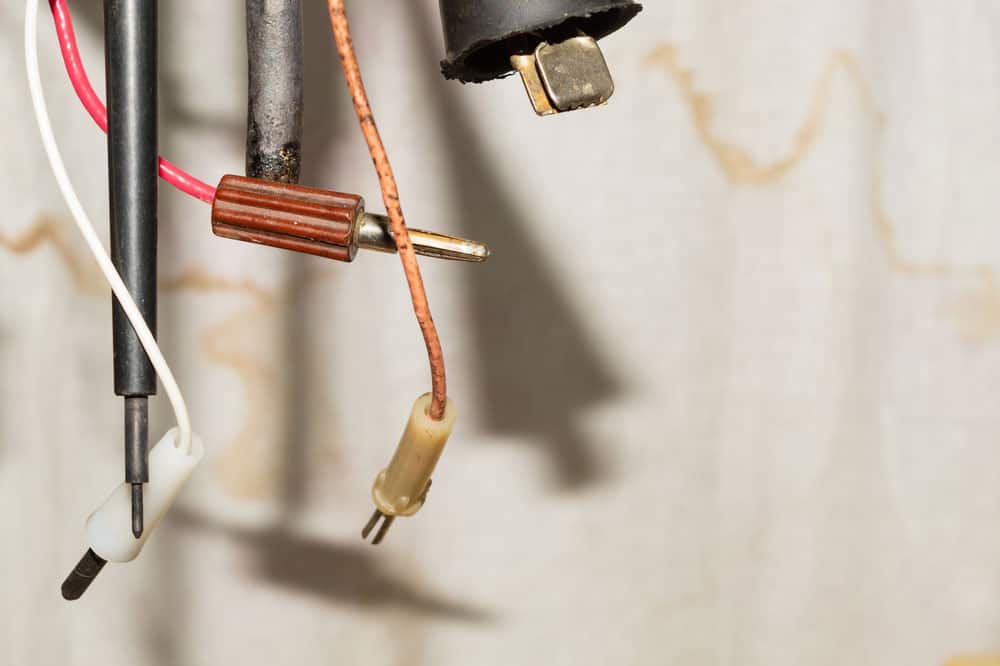
For the visual inspection, you’re visually inspecting the circuit breaker for damages resulting from arcing, wear and tear, or deformed contacts. After all, you want to detect and fix any potential problems that will limit adequate current flow.
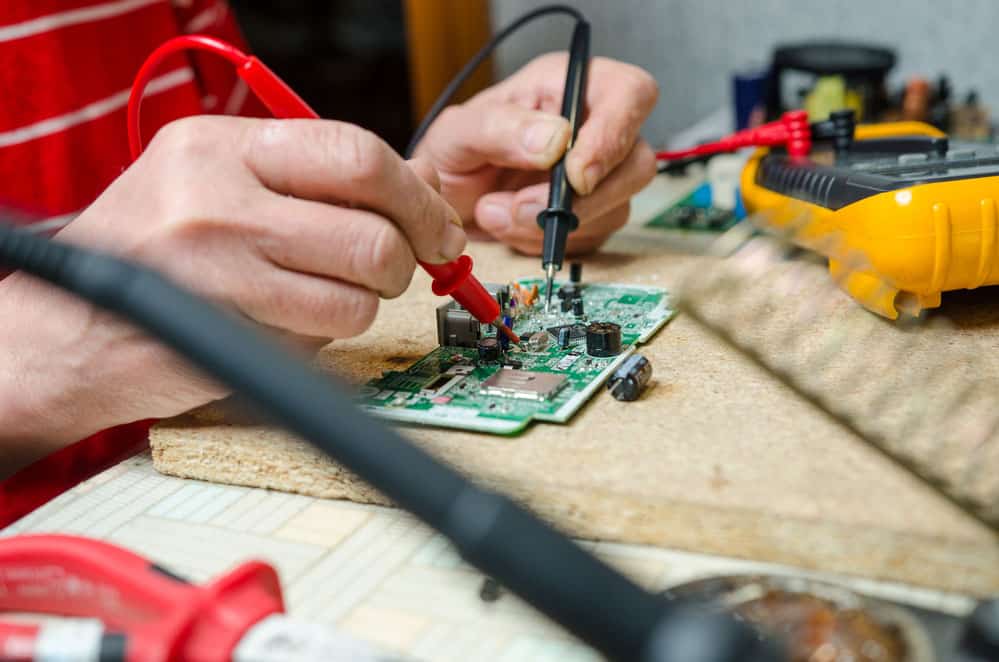
The instrumental inspection relies on the ohmmeter. You will apply a fixed amount of current to the contacts and measure the voltage across the circuit. The pressure can range from 100A, 200A or higher. Once the ohmmeter gives you an accurate measurement, you’ll finish calculating resistance using Ohm’s law. You can compare the value to the manufacturer’s and previous records to maintain acceptable contact resistance values.
Keep in mind that the visual and instrumental inspection happen concurrently to ensure the circuit is perfect.
Contact Resistance Test: Step-by-Step Guide
Before going further, you must have an ohmmeter or ductor tester to finish the contact resistance test. Most people use the micro- ohm meter because it provides a more accurate measurement. The ohmmeter will measure contact resistance using the four-wire (Kelvin) DC voltage drop, eliminating contact resistance and resistance to the current leads.
The test involves two potential leads for voltage drop measurements and two injection connections. Keep in mind that all voltage cables should connect highly close to the connection you’re testing. It would help if you also placed the cables within the circuit created by the connected current leads.
The microprocessor-controlled micro-ohmmeter will then calculate the contact resistance and eliminate errors caused by thermal EMF effects. After the results are in, you will add the contact resistance measurements to the total voltage drop measured separately.
Here’s a tip, make sure you subtract thermal EMF measurements from the final result to prevent inaccuracies. You can use various methods, including reversal of polarity, to measure thermal EMFs magnitude. In addition, if you record low readings while using low currents, it is advisable to re-do the test and apply a higher current. That’s because higher currents prevent connection problems and oxidation that occurs in terminals.
Additionally, always make sure your readings align with previous records and the manufacturer’s numbers. Even better, remember to keep a record of all your readings for future reference. Lastly, to maintain consistent results, you must perform the tests in the same position and conditions.
Conclusion
In conclusion, contact resistance tests are necessary to ensure your electrical connections are in tip-top shape. You don’t want to experience unexpected blackouts, equipment failure, or worse, fires caused by circuit breaker mishaps. So make a point to conduct regular tests and replace your contacts whenever you see fit.
Even better, you can contact Cloom for all your wiring and cabling needs. The company prides itself on ten years ofcustom cable assembly and wiring harness solutions.
Get Your Free Sample!
Explore our custom services now. Email us at [email protected] for more details.