When designing custom JST cable assembly, you’ll often need to use JST connectors. There’s much to know about to effectively use them for your project.
Get Your Free Sample!
Explore our custom services now. Email us at [email protected] for more details.
JST Connector Standards
It’s essential to mention some aspects of the JST connector standards that often confuse users. Firstly, there are ten families, each with subcategories and models. The term JST applies to the general solderless connection that all the connectors have in common, not a specifically categorized connector. To differentiate between the connectors, professionals normally use the JST-SS-D nomenclature to verify the names.
- JST: refers to the connector
- SS:refers to the family or series and sometimes is preceded by a different letter. An example is X, thus XSS. The preceding letter describes the connector’s shape and specifications (size, voltage, and current).
- D: refers to the dimensions within the series.

JST Connector Families
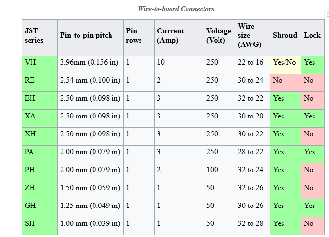
JST connectors are mostly identified by the length between one contact center to the next one. There are always more than two contacts in a single line. And some families have multiple rows. This length is the pitch of the connector and determines the connector family. For example, connectors in the family ‘PH’ all have a 2.00mm pitch. When identifying the type, you should determine the pitch value first. Next, you need to pay attention to the shape and size of the housing.
Below is a table to help you navigate types of wire-to-board connectors.
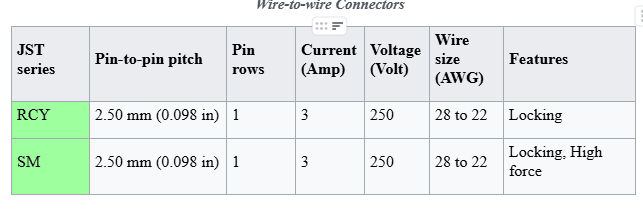
However, for wire-to-wire connectors, you’ll require different guidance. Below is the table to help you.
Get Your Free Sample!
Explore our custom services now. Email us at [email protected] for more details.
The application of JST cable assemblies
JST cable assemblies can be found in a wide variety of products across many industries.
JST SH
This wire connector has a spacing of about 1.5mm between the connecting pins. It features a 4-pin variant, a common JST connector often used in laptops and most flight controllers.
JST GH
Though similar to the SH connectors, the JST GH features a 1.25mm pin spacing. And if you take a closer look, you’ll notice the pins are bigger and spread wider apart. Also, the plastic housing is taller and thicker. Manufacturers designed the JST GH connectors for use in small video cameras. Despite the connectors having a different number of pins, the spacing is always a standard 1.25mm.
JST ZH
The JST ZH connector features a 1.5 mm pin spacing. These connectors are pretty rare compared to other connector types. Professionals use JST ZH connectors mainly in satellite receivers and, in some cases, 3D printers.
JST PH and PA
The JST PH and PA connectors feature a 2mm pin spacing. However, they differ in current capacity. The PH connector’s current capacity is 2 amps, while the PA connector has a current capacity of 3 amps. Professionals use these connectors in fabricated hobbyist PCBs and low-quality electronics primarily because of their low price and compact nature.
JST XH / XA /EH
The JST XH/ XA/ EH connectors have a pin spacing of about 2.5mm. The connector on the circuit determines the type of connector you’ll need, as each has a different number of input wires. In terms of current capacity, each connector offers the same capacity of 3 amps. Professionals often use these connectors for low-consumer products.
Although the connectors have similar characteristics, they come in different shapes. Therefore, you can use an EH instead of an XH. People consider the XH connectors a larger version of the previously mentioned PH connectors. The resemblance is in the head design and the tall plastic housing.
People rarely use the JST XA connectors since most projects require the XH connectors. Professionals mostly use JST XA connectors in Japanese-made LED TVs and other products.
How to Assemble the JST Connector with Wires Successfully?
Manually crimping JST connectors is challenging. Therefore, people often buy crimped wires that slip easily into the connector housing, creating any sequence. However, some people prefer to make their crimps. Read on to learn more about creating a crimp.
For a Good Crimp
Before diving straight into creating a crimp, let’s first discuss what a good crimp entails. When purchasing crimp connectors, you’ll notice some metal strips attached. These strips should go through a machine that automatically creates a crimp. However, we are looking to accomplish this manually.
Every crimp connector has two sets of wings you’ll need to bend as the process continues. The first set holds the insulation, while the second holds the wire. After the wires are crimped, they snap directly into the plastic housing, ganging them together. Upon pushing the wire inside the housing, you’ll hear a click. Just be careful not to cause too much damage to the crimp connector.
Crimping Tools
You’ll need to get a variety of tools to do the job. Ensure you get the best tools. Otherwise, you’ll need to crimp twice (first for the insulation and again for the wire). Also, ensure the tools are not hard to use to minimize room for errors. The key difference between the PA-20 and PA-09 is the scope of crimp sizes.
If you find the PA-09 ineffective, you could opt for the JST crimpers. The JST can crimp both wings at the same time while automatically positioning the crimp connector to its rightful position. However, it only works for one type of connector, the JST-PH.
Crimping Procedure
With crimping, you have to be careful to avoid mistakes. Although there’s no definite procedure for creating the crimp, below is a general flow to guide you.
- First, strip the ends of the wire and twist them a little bit. You’ll need a stripping tool to create a perfect strip of about 2 to 3 mm.
- The next step is to break the crimp connector away from the strand. Then, hold it in one of your hands and push the wire wings inside the appropriately sized tool. Make sure the crimp is pointing to the crimper as they bend backward. Also, ensure the outer insulation wings aren’t inside the crimper because you only want to crimp the inside wings of the first crimp. After this, don’t jump straight to crimping. Instead, push down slightly to ensure the crimp connection is held in the same position while using your other arm to lift the wire.
- Next, push the wire inside the crimp connection, ensuring the plastic insulation ends at the crimper’s edge without sticking out of the connection. Sometimes the connection might be too large to fit inside the connection or sides of the crimp to prevent it from slipping in.
- Now, the next step is to crimp. Ensure the wire strands stay beneath the folded wings while the outer wings remain open.
- Follow up by using the end of the crimp to slightly bend the outer wings so they can fit inside the crimping tool. Ensure that they’re parallel.
- Finally, put in the crimp connection from the opposite end and crimp.
Challenges:
- Over-crimping or bending the connection.
- Stripping too much or too little wire.
- Not pushing the wire far enough, and as a result, failing to crimp the insulation.
To ensure proper operation of the custom connector and prolong the connector’s lifespan, there are a couple of manufacturer suggestions to keep in mind:
- Ensure the JST cable is slightly longer than required to avoid cable stress.
- While disconnecting the JST cable connector, never pull on the wires, as you could loosen them up.
- Ensure you limit room for movement to about 15 degrees in every custom cable.
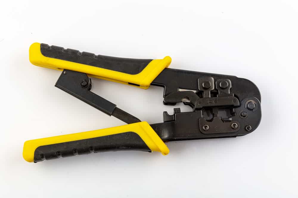
Caption: Crimp Tool
Conclusion:
There you have it all you need to know about JST cable assemblies. Feel free to reach out to Wiringo for all your custom cable assemblies. Our team of professionals has extensive experience, guaranteeing you get what you want.
Get Your Free Sample!
Explore our custom services now. Email us at [email protected] for more details.