Do you know what the basis of an electric device is? It’s the circuit. The circuit is a circular path having the same beginning and ending points. The current flows in a circuit from a power source and takes it to the electrical device. This current comes back to the power source. And here’s how the circuit completes itself.
The device works well until and unless there is a perfect continuity test of the current. If continuity breaks, the device stops working. It’s quite easy to check the continuity with the continuity test.
Now, let’s know what and how about this test in detail.
Get Your Free Sample!
Explore our custom services now. Email us at sales@wiringo.com for more details.
What is a continuity test?
As the name suggests, the continuity test checks the continuity of the current. Simply put, it checks if the current flows freely from one end to the other.
There are devices such as multimeters or ohmmeters to perform this test. You can also find some specialized continuity testers for the test. These testers are basic, low-cost, and have a bulb to indicate the current flow.
In this test, you provide a small voltage between the two testing points of the circuit. If something interrupts the current flow (or electrons), the circuit is open. The interruptions can be due to damaged components, cracked conductors, or high resistance. If there are no interruptions, it is a continuous circuit.
Get Your Free Sample!
Explore our custom services now. Email us at sales@wiringo.com for more details.
Why do you conduct a continuity test?
In electronics, continuity testing is quite important. You can perform this test to check various things within a circuit, such as:
- You can check the quality of soldering. Sometimes, soldering is a cold solder connection. Most of the time, you cannot identify it visually. Such soldering appears connected, but in reality, they are not.
- Sometimes, there are broken wires within the circuit. You can check the wire connection with the continuity test. This is especially important for power cords and headphone wires. These wires appear normal from the outside, but there can be some damage in reality.
- Also, identify any damaged components within the circuit.
- Do this test to know if two points have a connection in them or not, as in PCB.
- You can also verify the schematic diagram with the continuity test.
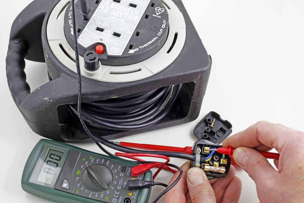
Image: Electric multimeter
How to test continuity with a multimeter:
As discussed above, you can use a multimeter to perform this test. To learn more about these safety tools, read further. First, understand the Multimeter or Ohmmeter.
This device can test various other electrical issues apart from testing the continuity of the electrical path.
You can test for AC/DC voltage, open circuit, short circuit, or amperage.
This is a rectangular tool with a dial or digital setting. With this dial, you can set the tool for the test you want to perform.
Like a continuity tester, a multimeter also powers through a battery.
You will find multiple holes at the front of the multimeter. Out of these, one is “COM,” which means short for “common.” This is for the ground. Another hole is mAVΩ, which means “measure amperage, voltage ohms. This is used to measure current. Apart from these two, there is a port of “10A”. You can use this for measuring very high currents.
It has two wire leads: red and black. You have to plug the black into the COM slot and the red into the mAVΩ slot of the multimeter. The other ends of the wires have metal probes.
Continuity Test for capacitor:
Before performing the test, you must remove the capacitor from the circuit and discharge it completely.
Test with continuity mode:
- First of all, set the dial to continuity mode.
- Secondly, plugin red and black probes into multimeter sockets as described above.
- Connect the other end of the multimeter’s red probe to the capacitor’s positive terminal.
- Following this, connect the capacitor’s negative terminal with the multimeter’s black probe.
- If the capacitor works well, the multimeter will show”0” initially. The multimeter charges the capacitor. With this, the reading reaches infinity or OL. The “OL” reading shows that the capacitor is open and charged completely.
- You will see a very low value (short) or infinity (open) in a damaged capacitor
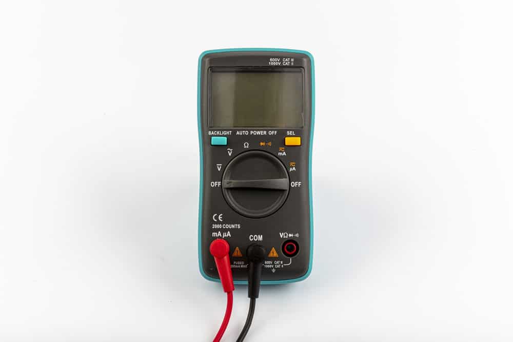
Image: continuity test for an extension cable
Test with resistance mode:
- First, set the multimeter to resistance mode.
- Connect the red and black probes to the positive and negative terminals of the capacitor.
- The capacitor is good if the resistance readings start from “0” and reach infinity. This shows that it was charging initially.
- If you get a very high initial resistance, it means the capacitor is damaged.
- If there is low resistance, your capacitor is short.
Continuity Test for Inductors:
An inductor is a coil; to test it, you must remove it from the circuit.
Test with continuity mode:
As described above, set the dial to continuity mode.
Plug red and black probes into multimeter COM and V-ohm sockets
Connect the red and black probes to the positive and negative terminals.
In case the inductor is working well, the multimeter will beep. You will see a very low value of readings. However, you cannot identify any short turns of the inductor.
In case of a damaged inductor, the multimeter will not beep and show “1” or “OL” readings indicating an open circuit.
Test with resistance mode:
First, set the multimeter to resistance mode. Try to adjust it to the lowest possible readings.
Secondly, connect the red and black probes to the positive and negative terminals of the inductor.
If the ohmmeter shows a few ohms resistance, the inductor is good.
And if you get very high initial resistance, the inductor is damaged.
Or if there is low resistance (near zero), the inductor might have short turns.
Test a Wire For Continuity With a Multimeter
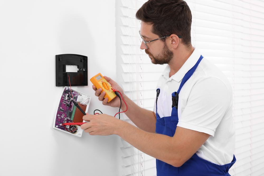
Caption: Testing For Continuity Using a Multimeter
- The first step is connecting the red and black terminals with the respective slots.
- Then, once you turn on the multimeter, set the dial on the device to test for continuity. However, if your device doesn’t seem to have a continuity setting, you may still do the test by setting the dial to the smallest amount in resistance mode.
- Now, make sure the device is working by touching the terminal’s metal parts together. Keep in mind:
- If the value you get on your multimeter is lower than one, then the device is properly functioning.
- Also, if the value is exactly zero, then the device is functioning.
- However, if the value you get is high or you don’t hear a beep, confirm the dial settings on your device. Next, inspect the ports you plugged into your terminals.
- Replace the terminals before checking the manual to determine how to reset your multimeter. If on the screen it displays one on the far left side and not the position values are normally displayed then it means you have a broken signal. A broken signal is an indication of faulty terminals.
- If the values keep fluctuating a bit, this is perfectly okay.
- Turn off and unplug the device you intend on testing. However, it’s obvious that you can not unplug a connected wire. Test the connected wire by turning off the vehicle, appliance, or device.
- Stick your black terminal on either end of your exposed wire. Ensure that the metal part at the end of your terminal is constantly in contact with the piece you want to test.
- Place your red terminal on a different part of your wire while keeping your black terminal on the first end of your current.
- Then, press the exposed red terminal on the opposite end of a linear current, such as the opposite end of your wire.
- Give the values some time to stabilize, then confirm the readings to determine the resistance. Note:
- If the reading is zero, this indicates perfect continuity.
- If the reading is lower, this indicates bad terminals or good continuity.
- If the reading is between 1 – 10, whether this is a problem depends on the device. Therefore, refer to the device’s manual to determine if this is an acceptable level of resistance. In the meantime you could play it safe and postpone using the device.
- If the reading is over 10, this indicates poor continuity. This means the resistance is higher than normal, and you should replace the wire.
- If you get no reading, this indicates that you have a broken circuit.
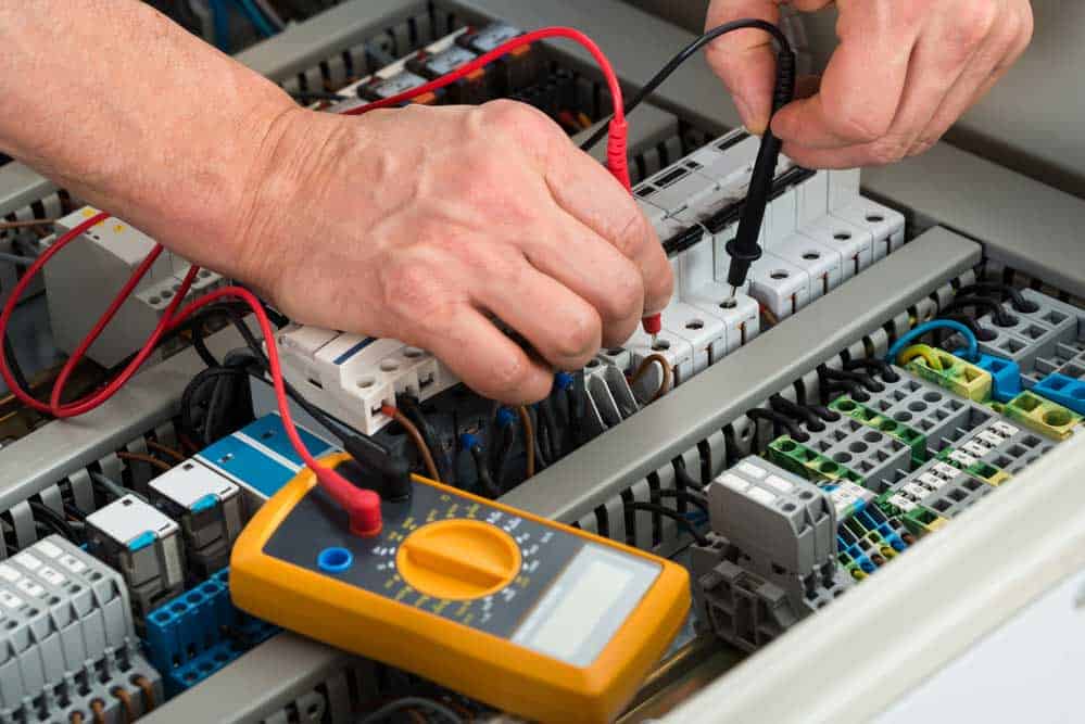
Image: Electrician checking the fuse box
Continuity Test for fuse:
Repeat the same process as you did with cables and wires.
The meter reading “zero” means the fuse is in good condition.
While an “infinite” reading means fuse continuity is broken.
Continuity Test for switch/push buttons:
You can conduct the same test as above for switches and push buttons.
However, in this case, you need to do the test in both “on” and “off” conditions.
Firstly, take the reading in the “ON” mode. Secondly, repeat the process for the “OFF” mode.
In the first test, you must get “zero” and “infinite” for the second test.
This means your switch and push-button are in good condition.
On the other hand, if both readings are “0” or “infinite,” the switch is in a short circuit.
In this case, you must replace the switch/push button.
How to Test Continuity without A Multimeter:
You can use a Continuity Tester for testing metal pathways.
A battery is the source of power for this tester. You will find a metal probe at one end of this tool. On the other end, there is a wire lead, which either has an alligator clip or a probe.
Its working is quite simple. Just touch the metal probe and wire lead with each other.
If the circuit is complete, the light or buzzer will go off. You can also find an LED or any other visual indication in some devices.
Similarly, you can test the electrical path for a device, appliance, or circuit.
Ensure that the power supply is off before using this tester, as using it on live wires is dangerous.
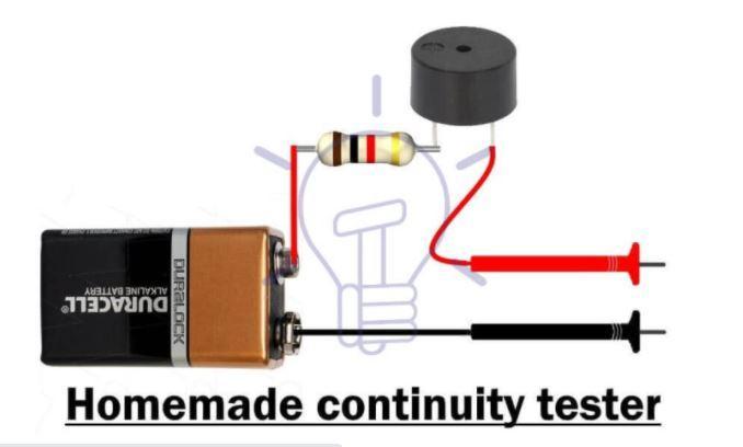
If you do not have one, no worries. You can make a Homemade Continuity Tester.
Get a 9v battery, buzzer or LED resistor, and two wires. Connect them as shown in the figure. Your continuity tester is ready.
Conclusion:
Testing the continuity of circuits is vital for major electronics repair. Checking the circuit continuity helps you pinpoint any issues with the integrity of the circuit. However, to prevent any issues with your electrical devices, you must start early.
Go for high-quality cable assemblies and wiring harnesses. Wiringo offers you the best solution for wire assemblies.
Get Your Free Sample!
Explore our custom services now. Email us at sales@wiringo.com for more details.