All vehicles in the automotive industry use wiring harness setups. If you are riding a motorcycle or another two or three-wheeler, it will have this assembly.
Furthermore, it’s standard in cars, RVs, and other commercial and utility vehicles.
Automotive wiring should fit the electrical specifics of your car. That’s why sometimes people choose chassis wiring in the automotive industry.
So, start reading to learn how to ensure an optimal assembly! After reading the article, you’ll discover the potential uses of these setups.
Get Your Free Sample!
Explore our custom services now. Email us at [email protected] for more details.
Understanding Chassis Wiring Based On Power Transmission Wiring
Chassis wiring is the electrical components within a piece of machinery or vehicle, including the wiring connecting sensors, lights, and other various accessories to the power source of your vehicle.
Manufacturers design the chassis wiring to handle all the electrical demands of your vehicle’s accessories and internal systems.
On the other hand, power transmission wiring refers to the amount of electrical current flowing through your power transmission cables or lines.
This is in relation to electricity transmission from the power generation source, like a power plant, to distribution points or end users.
The amperage of power transmission lines is vital in determining an electrical grid’s capacity to deliver power to businesses, industrial facilities, and homes.
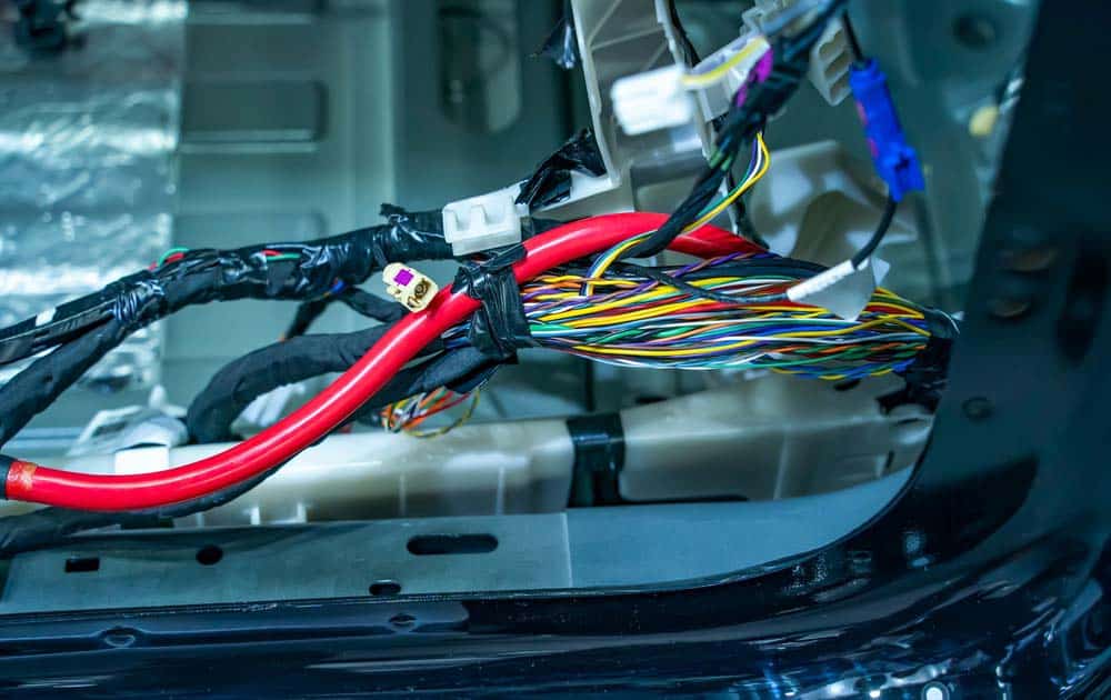
Caption: Chassis Wiring
The amp capability of Chassis Wiring matters a lot.
The term ampacity is a shortened version of ampere capacity. So, this describes the maximum current that a cable can handle. Furthermore, it refers to the current you can transfer safely.
If you check out a cable, you’ll find the following components:
- A conductor (usually made of copper)
- Wire insulation around it
The more current you transfer, the hotter the conductor gets. If you assess the ampacity of chassis wiring, you’ll know the needed temperature rating and wire size.
A smaller cable rating could lead to burning the wires. Furthermore, they can cause fires and colossal damage.
That’s why it’s crucial to get the desired ampacity and choose cables accordingly.
You set the wire ampacity based on the current limits that go through the wire at 30C. The National Electrical Code offers the starting points for different conductors.
You can adjust these based on the duty cycle, ambient temperature, and specific system demands.
Get Your Free Sample!
Explore our custom services now. Email us at [email protected] for more details.
Find The Amp Capacity Of Your Chassis Wiring Based on The AWG
Below is a table to help you determine the amp capacity of your chassis wiring in relation to AWG.
| AWG Gauge | Conductor Diameter (mm) | Conductor Diameter (inches) | Conductor Cross-section (mm2) | Max Amps For Power Transmission | Max Amps For Chassis Wiring |
| 0000 | 11.684 | 0.46 | 107 | 302 | 380 |
| 000 | 10.40384 | 0.4096 | 84.9 | 239 | 328 |
| 00 | 9.26592 | 0.3648 | 67.4 | 190 | 283 |
| 0 | 8.25246 | 0.3249 | 53.5 | 150 | 245 |
| 1 | 7.34822 | 0.2893 | 42.4 | 119 | 211 |
| 2 | 6.54304 | 0.2576 | 33.6 | 94 | 181 |
| 3 | 5.82676 | 0.2294 | 26.7 | 75 | 158 |
| 4 | 5.18922 | 0.2043 | 21.1 | 60 | 135 |
| 5 | 4.62026 | 0.1819 | 16.8 | 47 | 118 |
| 6 | 4.1148 | 0.162 | 13.3 | 37 | 101 |
| 7 | 3.66522 | 0.1443 | 10.6 | 30 | 89 |
| 8 | 3.2639 | 0.1285 | 8.37 | 24 | 73 |
| 9 | 2.90576 | 0.1144 | 6.63 | 19 | 64 |
| 10 | 2.58826 | 0.1019 | 5.26 | 15 | 55 |
| 11 | 2.30378 | 0.0907 | 4.17 | 12 | 47 |
| 12 | 2.05232 | 0.0808 | 3.31 | 9.3 | 41 |
| 13 | 1.8828 | 0.072 | 2.63 | 7.4 | 35 |
| 14 | 1.62814 | 0.0641 | 2.08 | 5.9 | 32 |
| 15 | 1.45034 | 0.0571 | 1.65 | 4.7 | 28 |
| 16 | 1.29032 | 0.0508 | 1.31 | 3.7 | 22 |
| 17 | 1.15062 | 0.0453 | 1.04 | 2.9 | 19 |
| 18 | 1.02362 | 0.0403 | 0.823 | 2.3 | 16 |
| 19 | 0.91186 | 0.0359 | 0.653 | 1.8 | 14 |
| 20 | 0.8128 | 0.032 | 0.519 | 1.5 | 11 |
| 21 | 0.7239 | 0.0285 | 0.412 | 1.2 | 9 |
| 22 | 0.64516 | 0.0253 | 0.327 | 0.92 | 7 |
| 23 | 0.57404 | 0.0225 | 0.259 | 0.729 | 4.7 |
| 24 | 0.51054 | 0.0201 | 0.205 | 0.577 | 3.5 |
| 25 | 0.45466 | 0.0179 | 0.162 | 0.457 | 2.7 |
| 26 | 0.40386 | 0.0159 | 0.128 | 0.361 | 2.2 |
| 27 | 0.36086 | 0.0142 | 0.102 | 0.288 | 1.7 |
| 28 | 0.32004 | 0.0126 | 0.080 | 0.226 | 1.4 |
| 29 | 0.28702 | 0.0113 | 0.0647 | 0.182 | 1.2 |
| 30 | 0.254 | 0.01 | 0.0507 | 0.142 | 0.86 |
| 31 | 0.22606 | 0.0089 | 0.0401 | 0.113 | 0.7 |
| 32 | 0.2032 | 0.008 | 0.0324 | 0.091 | 0.53 |
| Metric 2.0 | 0.200 | 0.00787 | 0.0314 | 0.088 | 0.51 |
| 33 | 0.18034 | 0.0071 | 0.0255 | 0.072 | 0.43 |
| Metric 1.8 | 0.180 | 0.00709 | 0.0254 | 0.072 | 0.43 |
| 34 | 0.16002 | 0.0063 | 0.0201 | 0.056 | 0.33 |
| Metric 1.6 | 0.16002 | 0.0063 | 0.0201 | 0.056 | 0.33 |
| 35 | 0.14224 | 0.0056 | 0.0159 | 0.044 | 0.27 |
| Metric 1.4 | 0.140 | 0.00551 | 0.0154 | 0.043 | 0.26 |
| 36 | 0.127 | 0.005 | 0.0127 | 0.035 | 0.21 |
| Metric 1.25 | 0.125 | 0.00492 | 0.0123 | 0.034 | 0.20 |
| 37 | 0.1143 | 0.0045 | 0.0103 | 0.0289 | 0.17 |
| Metric 1.12 | 0.112 | 0.00441 | 0.00985 | 0.0277 | 0.163 |
| 38 | 0.1016 | 0.004 | 0.00811 | 0.0228 | 0.13 |
| Metric 1 | 0.1000 | 0.00394 | 0.00785 | 0.0225 | 0.126 |
| 39 | 0.0889 | 0.0035 | 0.00621 | 0.0175 | 0.11 |
| 40 | 0.07874 | 0.0031 | 0.00487 | 0.0137 | 0.09 |
AWG: In the AWG (American Wire Gauge) system, you can calculate wire size diameter by applying the following formula: D(AWG)=.005·92((36-AWG)/39) inch.
In instances where the AWG is 0000, 000, or 00, you can use -3, -3, -1, which makes more mathematical sense than double naught.
Therefore, in the AWG system, a 6 gauge decrease results in the wire diameter doubling, while a 3 gauge decrease doubles the cross-sectional area of the wire.
If that’s the case, you can use the following formula: D = .460 * (0.890625)(AWG +3)
Metric Gauge: In the metric scale, the gauge is X10, and the diameter is in mm. Therefore, a 50 gauge metric should be 5 millimeters in diameter. Keep in mind that with AWG, the diameter increases as the gauge decreases, while with metric gauges, it’s the opposite.
Rated Ampacities: The rated ampacity is simply a rule of thumb. In proper engineering, insulation temperature limit, voltage drop, thermal conductivity, thickness, temperature, and air convection should all be considered.
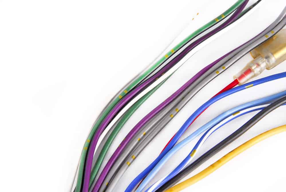
Caption: A car’s audio system wiring cable
What Are the Chassis Wiring Uses in A Car?
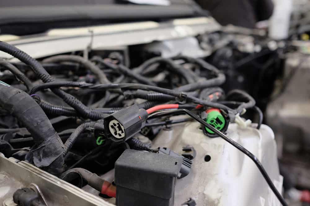
Caption: Automotive wiring close up
Chassis wiring is a bundle of wires placed to interconnect assemblies inside a cabinet where a wire is stand-alone and exposed to the open air. When it comes to vehicles, we often see it in:
Main Harness
This is the primary harness. After the setup, it secures the user can adjust electronic gear and multimedia. Therefore, it comes with a control panel or switch. The applications for this harness go from GPS to radio, DVD, and other multimedia.
Front Harness
This setup attaches the inner engine’s side to the inside of your vehicle. Therefore, you often find it in engine controllers and AC fans. While keeping your AC clean is essential, this is crucial for it even to work. A front harness also serves temperature, current power, speed limit, pedal, and other sensors.
Rear Harness
The third component of the chassis wiring is the rear harness. The name suggests it goes into the back of a vehicle, but it also connects to the main element. Frequent use is for fuel levels, but the rear harness has other purposes, too.
Note: The chassis wiring diagrams could be different. The Ford F53 chassis wiring schematic is different from that of other cars. So, make sure to choose a suitable option.
Also, here is a quick overview of the benefits of having a harness:
- It comes with a minimal shorting risk. So, you’ll have everything aligned, which reduces the chance of something going wrong. It’s a better option than loose wires.
- It’s suitable for harsh environments. You want premium materials for your harness. Therefore, they’ll be long-lasting and keep consistent performance.
- It has improved performance and fuel efficiency. Your vehicle is likely to spend less fuel with optimized wiring. Performance can often be better, especially in hybrid and electric cars.
How to Test, Repair, and Replace Chassis Wiring
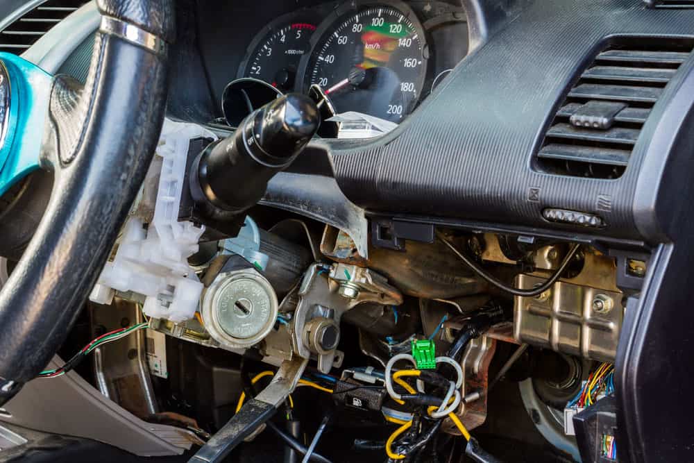
Caption: Car electric repair
If you already have a chassis wiring setup in your car, you want to ensure everything works right!
What to Do to Test Your Chassis Wiring?
There aren’t exact rules for testing how the setup works. So, you want to rely on your senses.
Did you notice something is wrong with the assembly? It might be a foul smell coming from that part of the vehicle.
Some functions might not be working correctly. Your nose can lead you to the burned wire if it’s the smell. Therefore, follow the scent, and you’ll easily find the damage.
Don’t forget to rely on your eyes. So, a visual inspection can take you a long way. Do you notice a cut wire?
Is there a problem in connecting one section to another? If you see visible damage, that’s where the problem lies.
On the other hand, what if you need to detect opens, shorts, or grounds? That’s where signal tracing is proper. Therefore, rely on this method and don’t forget to consult the instruction manual.
How to Repair Your Chassis Wiring
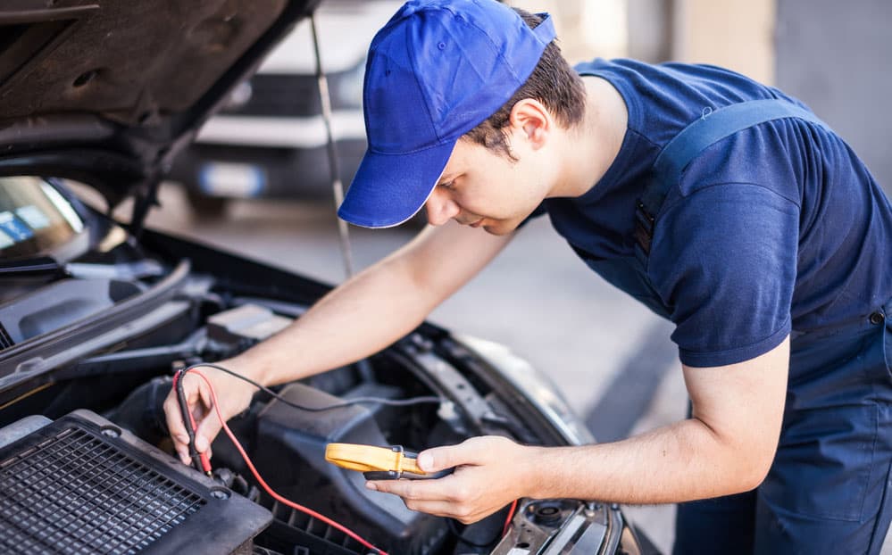
Caption: A mechanic troubleshooting car’s engine
The initial assessment should determine if the repair is worth it. Does it seem like a minor fix that won’t take much of your time? Furthermore, are the new materials you need expensive?
You can also apply a temporary fix until you find a permanent solution. So, you’ll need a straight wire where the initial cables were going.
Make sure to detach the faulty lead before attaching the new one. Furthermore, it would help if you soldered the new information.
That should be easy with a soldering iron. This is a quick fix that shouldn’t last a long time. On the other hand, it’s convenient when you don’t have much time available.
What if you need to replace many wires? You can connect them separately from the initial setup. So, detach any faulty wiring first.
The new installation should follow the same route, and don’t forget to clamp them to keep them tight.
A Guide to Replacing Your Chassis Wiring
These setups are usually durable. However, the abrasion and friction in performing other repairs might cause damage to it. So, if you notice that the chassis wiring failed, it might be time for a replacement.
This project takes patience because you need to change each wire separately. Furthermore, a soldering iron is a necessary equipment piece.
It helps to get a custom harness for your vehicle. That way, you can repair the entire assembly instead of changing each wire.
You’ll need a suitable wiring diagram to determine the required size.
Furthermore, it helps to take a photo of the faulty harness before replacing it. That will assist in determining each wire’s position.
Conclusion
You are now familiar with how chassis wiring works and what repairs and replacements involve. If you need any advice on cable assemblies, don’t hesitate to contact our experts!
Get Your Free Sample!
Explore our custom services now. Email us at [email protected] for more details.